Ford Air Bypass Valve Diagram - Thermactor Inlet, Outlet & Vent Ports (A6002-H)

Reference · 1992-1996 BroncoAll 95 schematics
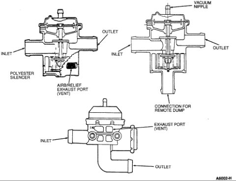





Cutaway schematic of air bypass/diverter valves showing inlet, outlet, vacuum nipple, and exhaust vent ports.
Part of 1992-1996 Ford Bronco Schematics
This document is a technical line-art schematic (Ford figure reference A6002-H) showing cutaway and external views of three styles of air bypass/diverter valves used in an engine's Thermactor-type secondary air injection system. The upper-left cutaway view identifies the valve's inlet, outlet, polyester silencer, and the air bypass/relief exhaust port (vent). The upper-right cutaway view shows a similar valve with its vacuum nipple on top, inlet and outlet ports, and a lower connection for a remote dump. The bottom view is an external perspective drawing of a third valve style, labeling the inlet, outlet, and exhaust port (vent). A reader can learn where air enters and exits each valve type, where vacuum control is applied, where excess air is vented (through the polyester silencer or exhaust/vent port), and how a remote-dump style valve differs from a vented style. No year, model, engine, torque values, or part numbers other than the figure code A6002-H are shown. The document was uploaded to a 1995 Ford Bronco gallery, and nothing in the drawing contradicts that application, though the drawing itself states no applicability.
Is this accurate? Sign in to help verify it.
Frequently asked questions
- What parts of the air bypass valve are labeled in this diagram?
- The diagram labels the inlet, outlet, vacuum nipple, polyester silencer, air bypass/relief exhaust port (vent), exhaust port (vent), and a connection for remote dump.
- Where is the vacuum nipple located on the valve?
- The vacuum nipple is shown at the top of the upper-right valve, above the diaphragm housing.
- What is the polyester silencer for?
- The diagram shows the polyester silencer positioned at the air bypass/relief exhaust port (vent) on the upper-left valve, where excess air is vented.
- How does the remote-dump valve differ from the others shown?
- The upper-right valve has a downward-facing connection labeled 'connection for remote dump' instead of venting through an exhaust port with a silencer.
- Is there a figure or reference number on this diagram?
- Yes, the figure reference 'A6002-H' appears in the lower right corner.






No comments yet.