Home/
Registry/
Ford/
Bronco/
1992-1996/
1996 Ford Bronco/
Photo
supermotors.net/registry/media/1073513
Ford Bronco VSS to PCM Wiring Schematic - PSOM, ABS & Speed Sensor Circuits
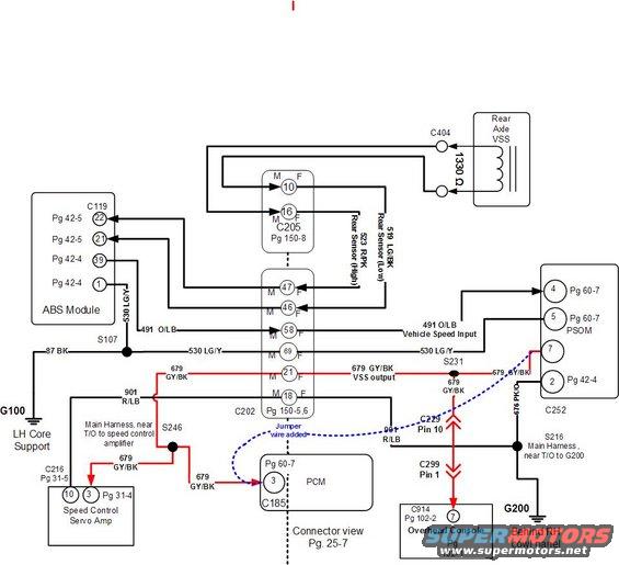
Vehicle speed sensor wiring detail showing the 1330-ohm rear axle VSS, ABS module, PSOM, PCM and overhead console connections with 491 vehicle speed input and 679 GY/BK VSS output wires.
Part of 1992-1996 Ford Bronco Wiring Diagrams
This document is a redrawn/annotated wiring schematic showing the vehicle speed sensor (VSS) signal path in a Ford Bronco. The Rear Axle VSS (1330 Ω sensor at connector C404) feeds through connector C205 (pins 10 and 16) via circuits 519 LG/BK (Rear Sensor Low) and 523 RPK (Rear Sensor High) to the ABS Module at connector C119 (pins 22, 21, 39, 1). From connector C202 (pins 47, 46, 58, 69, 21, 18), circuit 491 O/LB carries Vehicle Speed Input and circuit 679 GY/BK carries VSS output to the PSOM at connector C252 (pins 4, 5, 7, 2). Circuit 679 GY/BK branches through splices S231 and S246 to the Speed Control Servo Amp (C216) and to the PCM at connector C185 pin 3, with a highlighted "jumper wire added" modification shown from PSOM pin 7 to the PCM. Grounds shown include G100 at the LH core support (circuit 87 BK via splice S107) and G200 behind the RH cowl panel (circuit 676 PK/O via splice S216). A path through C229 pin 10 and C299 pin 1 feeds the Overhead Console (C914 pin 7). EVTM page references are given for each component and connector.
Is this accurate? Sign in to help verify it.
Frequently asked questions
- What wire carries the VSS output signal to the PCM on this diagram?
- Circuit 679 GY/BK (gray/black) carries the VSS output from C202 pin 21 through splices S231 and S246 to the PCM at connector C185 pin 3, and also to the Speed Control Servo Amp.
- What is the resistance of the rear axle VSS?
- The Rear Axle VSS is labeled 1330 Ω, connected at connector C404.
- Which wires are the rear speed sensor high and low circuits?
- Circuit 523 RPK is the Rear Sensor (High) and circuit 519 LG/BK is the Rear Sensor (Low), passing through connector C205 pins 10 and 16.
- Which PCM connector and pin receives the vehicle speed signal?
- The diagram shows the speed signal going to PCM connector C185, pin 3 (referenced to Pg 60-7), with a note that a jumper wire was added from PSOM connector C252 pin 7.
- Where are the grounds G100 and G200 located?
- G100 is at the LH core support (via circuit 87 BK and splice S107), and G200 is behind the RH cowl panel (via circuit 676 PK/O and splice S216, Main Harness near T/O to G200).
Comments
More from this build












No comments yet.