Home/
Registry/
Ford/
Bronco/
1992-1996/
1996 Ford Bronco/
Photo
supermotors.net/registry/media/898846
1996 Ford Bronco/F-150 Overhead Console Wiring Diagram - Compass/Temp Display

Reference · 1992-1996 BroncoAll 411 wiring diagrams
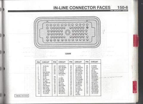
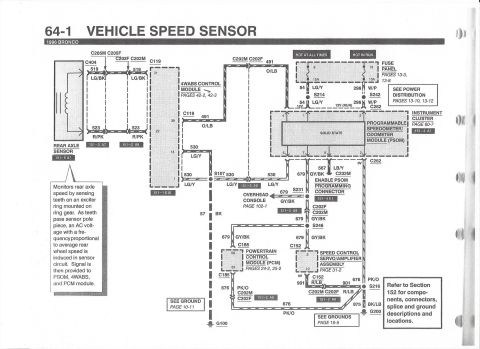
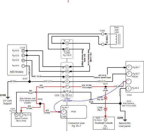
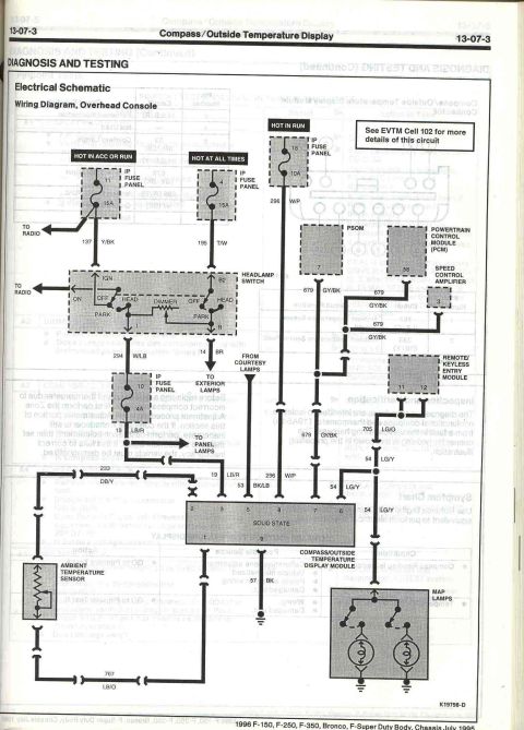
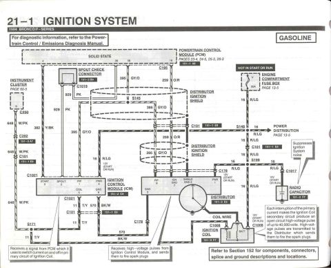
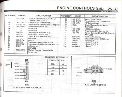
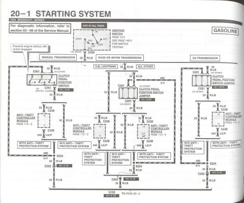
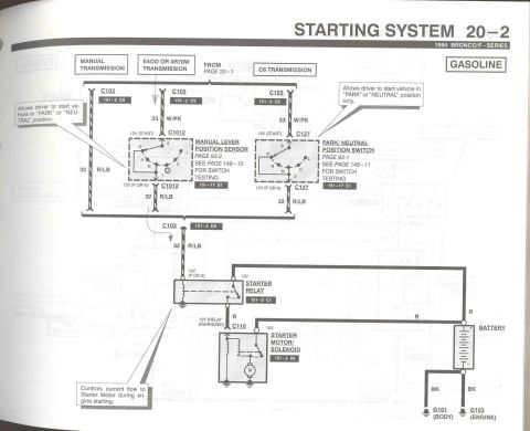

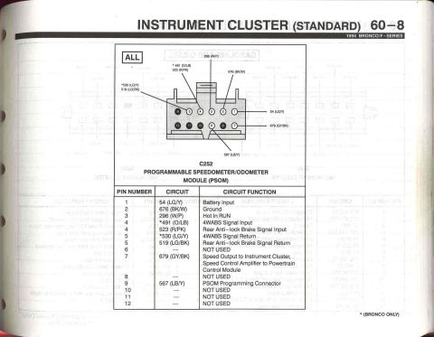
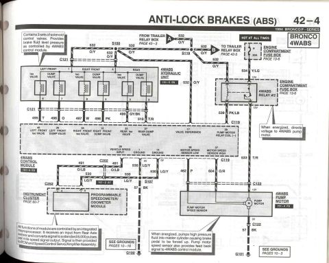
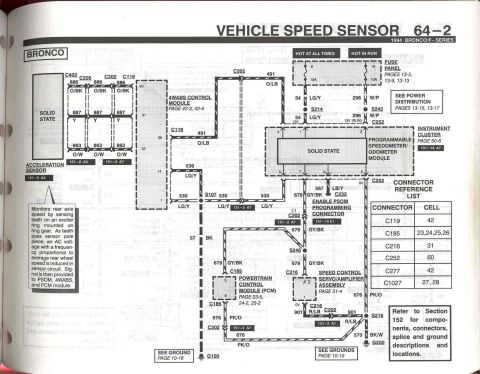



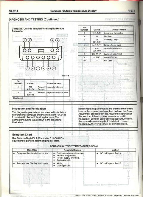



Electrical schematic for the overhead-console compass/outside-temperature display, showing the ambient temperature sensor, map lamps, headlamp switch and PCM/PSOM connections.
Part of 1992-1996 Ford Bronco Wiring Diagrams
This is page 13-07-3 from the 1996 Ford Body/Chassis service manual (F-150, F-250, F-350, Bronco, F-Super Duty; dated July 1995), covering Diagnosis and Testing of the Compass/Outside Temperature Display. It presents the electrical schematic / wiring diagram for the overhead console. The diagram shows three power feeds from the instrument panel (IP) fuse panel: fuse 11 (15A, hot in ACC or RUN, circuit 137 Y/BK, shared with the radio), fuse 4 (15A, hot at all times, circuit 195 T/W), and fuse 18 (10A, hot in RUN, circuit 296 W/P). Power routes through the headlamp switch and fuse 10 (4A) on circuit 19 LB/R for panel-lamp dimming. The solid-state compass/outside temperature display module connects to the ambient temperature sensor (circuits 233 DB/Y and 767 LB/O), courtesy lamps (53 BK/LB), the PSOM/PCM/speed control amplifier speed signal (679 GY/BK), the remote/keyless entry module (705 LG/O, 54 LG/Y), and the map lamps (54 LG/Y), with ground on circuit 57 BK. A note directs readers to EVTM Cell 102 for more circuit detail. Diagram reference number K19798-D appears at the bottom. Useful for diagnosing overhead console compass/temperature display, map lamp, and dimming faults.
Is this accurate? Sign in to help verify it.
Frequently asked questions
- Which fuses power the overhead console compass/outside temperature display on a 1996 Ford Bronco or F-Series?
- Three IP fuse panel fuses feed the circuit: fuse 11 (15A, hot in ACC or RUN, circuit 137 Y/BK), fuse 4 (15A, hot at all times, circuit 195 T/W), and fuse 18 (10A, hot in RUN, circuit 296 W/P). Fuse 10 (4A) feeds the panel lamp dimming circuit 19 LB/R through the headlamp switch.
- What wire colors connect the ambient temperature sensor to the display module?
- The ambient temperature sensor connects via circuit 233 DB/Y (dark blue/yellow) and circuit 767 LB/O (light blue/orange).
- What provides the vehicle speed signal to the compass/outside temperature display module?
- Circuit 679 GY/BK, which is shared with the PSOM (pin 7), the Powertrain Control Module (pin 58), and the Speed Control Amplifier (pin 3), feeds pin 7 of the display module.
- Where can more detail on this overhead console circuit be found?
- The diagram notes: 'See EVTM Cell 102 for more details of this circuit.'
- What circuit runs the map lamps in the overhead console?
- The map lamps are fed by circuit 54 LG/Y, which also connects to the remote/keyless entry module (along with circuit 705 LG/O) and pin 6 of the display module.






No comments yet.