Home/
Registry/
Ford/
Bronco/
1992-1996/
“Eddie Bauer”/
Photo
supermotors.net/registry/media/1157086
1994 Ford Bronco 4WABS ABS Wiring Diagram - EVTM Page 42-4

Reference · 1992-1996 BroncoAll 411 wiring diagrams

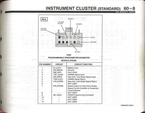
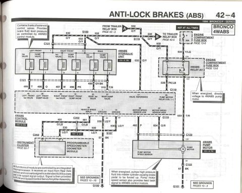
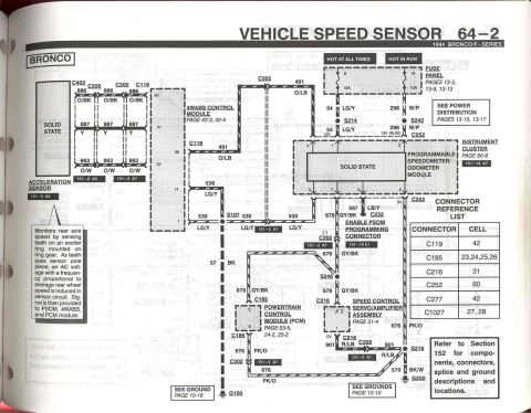














1994 Bronco/F-Series rear anti-lock brake (4WABS) schematic: hydraulic control valve solenoids, dump valves, wheel-speed sensors, pump motor relay, 4WABS control module and PSOM speedometer module.
Part of 1992-1996 Ford Bronco Wiring Diagrams
This is page 42-4 of the 1994 Ford Bronco/F-Series Electrical and Vacuum Troubleshooting Manual (EVTM), showing the Bronco 4-Wheel Anti-lock Brake System (4WABS) wiring diagram. It details the 4WABS hydraulic unit containing three sets of solenoid iso/dump valves (left front, right front, rear) with connector C121 pinouts and wire circuits 495 T, 496 O, 497 W, 498 PK, 499 GY/BK, and 510 T/R feeding the 4WABS control module (grid 151-4 E9). Power comes from a 30A fuse (position H) in the engine compartment fuse box on circuit 532 O/Y, which also links to the trailer relay box (pages 42-3 and 42-5). 4WABS Relay #2, when energized, directs voltage (circuit 534 Y/LG in, 539 PK/LB and 533 T/R control) to the 4WABS pump motor, which pumps high-pressure fluid into the master cylinder; the pump motor speed sensor (circuits 462 P and 604 O/R) provides feedback to the control module. The programmable speedometer/odometer module provides an 8,000 pulses-per-mile vehicle speed signal (circuits 491 O/LB, 530 LG/Y) to the module, PCM, and speed control servo. Grounds are at G100 and G101 via wire 57 BK. Cross-references include fuse box page 13-6 and instrument cluster page 60-7.
Is this accurate? Sign in to help verify it.
Frequently asked questions
- What fuse powers the 1994 Bronco 4WABS system?
- A 30A fuse in position H of the engine compartment fuse box (hot at all times), feeding circuit 532 O/Y. The fuse box layout is on page 13-6.
- What wire colors connect the 4WABS hydraulic unit valves to the control module?
- Through connector C121: 495 T (left front iso), 496 O (left front dump), 497 W (right front iso), 498 PK (right front dump), 499 GY/BK (rear iso), and 510 T/R (rear dump).
- What does 4WABS Relay #2 do?
- When energized, it directs 12V voltage to the 4WABS pump motor. It receives power on circuit 534 Y/LG, and its coil is controlled by the module on circuit 533 T/R via C119.
- What does the 4WABS pump motor do when energized?
- It pumps high pressure fluid into the master cylinder, causing the brake pedal to be forced up. Its speed sensor also provides feedback (wires 462 P and 604 O/R) to the 4WABS control module.
- How does the speed signal reach the 4WABS control module?
- The programmable speedometer/odometer module receives input from the rear axle sensor, converts it to a standard 8,000 pulses per mile signal, and provides it to the module (pin 39, vehicle speed input via circuits 491 O/LB and 530 LG/Y), the PCM, and the speed control servo/amplifier assembly.






No comments yet.