Home/
Registry/
Ford/
Bronco/
1992-1996/
“Eddie Bauer”/
Photo
supermotors.net/registry/media/1157087
1994 Ford Bronco/F-Series PSOM C252 Connector Pinout - Speedometer Wiring

Instrument cluster C252 connector pinout chart and PSOM wiring detail for the 1994 Bronco/F-Series.
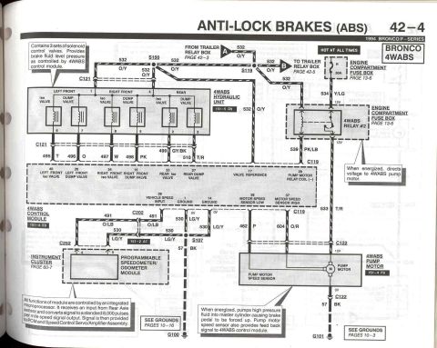
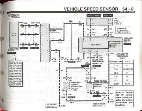
This page (60-8) from the 1994 Ford Bronco/F-Series Electrical & Vacuum Troubleshooting Manual covers the standard instrument cluster, specifically connector C252 for the Programmable Speedometer/Odometer Module (PSOM). A diagram of the 12-pin connector (applicable to "ALL" models) shows pin positions 1-6 on the top row and 7-12 on the bottom row, with wire circuit numbers and color codes labeled: 54 (LG/Y), 676 (BK/W), 296 (W/P), 491 (O/LB), 523 (R/PK), 530 (LG/Y), 519 (LG/BK), 679 (GY/BK), and 567 (LB/Y). A pinout table defines each circuit's function: pin 1 battery input, pin 2 ground, pin 3 hot in RUN, pin 4 4WABS signal input (491, Bronco only) or rear anti-lock brake signal input (523), pin 5 4WABS signal return (530, Bronco only) or rear anti-lock brake signal return (519), pin 7 speed output to instrument cluster/speed control amplifier/powertrain control module, pin 9 PSOM programming connector (567), and pins 6, 8, 10, 11, 12 not used. Circuits marked with an asterisk apply to Bronco only. Useful for diagnosing speedometer, odometer, cruise control, or ABS speed-signal issues.
Is this accurate? Sign in to help verify it.
Frequently asked questions
- What is connector C252 on a 1994 Ford Bronco/F-Series?
- C252 is the connector for the Programmable Speedometer/Odometer Module (PSOM), a 12-pin connector shown on page 60-8 of the instrument cluster (standard) section.
- Which PSOM pin carries the vehicle speed output?
- Pin 7, circuit 679 (GY/BK), carries speed output to the instrument cluster and speed control amplifier to the powertrain control module.
- What are the power and ground pins on the PSOM connector?
- Pin 1 is battery input on circuit 54 (LG/Y), pin 2 is ground on circuit 676 (BK/W), and pin 3 is hot in RUN on circuit 296 (W/P).
- Which PSOM circuits are Bronco only?
- Circuits marked with an asterisk are Bronco only: 491 (O/LB) 4WABS Signal Input on pin 4 and 530 (LG/Y) 4WABS Signal Return on pin 5.
- Which pins on the PSOM connector are not used?
- Pins 6, 8, 10, 11, and 12 are listed as NOT USED.
Comments
More from this build







No comments yet.