Home/
Registry/
Hyundai/
Genesis Coupe/
2010-2016/
“Coupe”/
Photo
supermotors.net/registry/media/1107548
Hyundai Genesis Coupe Interior Fuse Box Diagram 91941-2M020 - Fuse Map & Amps

Reference · 2010-2016 Genesis CoupeAll 11 fuse & relay charts

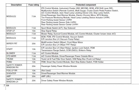
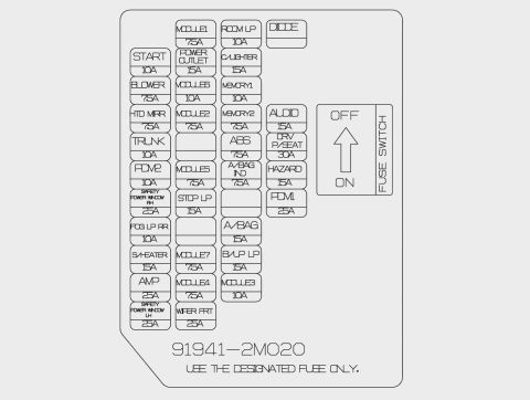
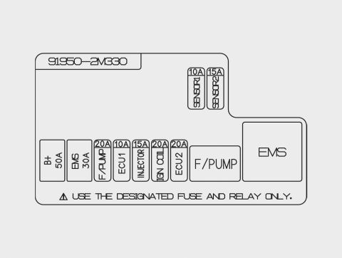
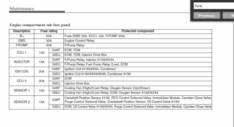








Passenger compartment fuse box diagram mapping fuse positions, circuit names and amperage ratings.
Part of 2010-2016 Hyundai Genesis Coupe Fuse & Relay Charts
This document is a scanned interior fuse box map (fuse panel lid label) showing the layout of fuses in the driver-side interior junction box. Each fuse position is labeled with its circuit name and amperage rating. Circuits shown include START (10A), BLOWER (7.5A), HTD MIRR (7.5A), TRUNK (10A), PDM2 (10A), SAFETY POWER WINDOW RH and LH (25A each), FOG LP RR (10A), S/HEATER (15A), AMP (25A), MODULE1-MODULE7 (7.5A-10A), POWER OUTLET (15A), STOP LP (15A), WIPER FRT (25A), ROOM LP (10A), C/LIGHTER (15A), MEMORY1 (10A), MEMORY2 (7.5A), ABS (7.5A), A/BAG IND (7.5A), A/BAG (15A), B/UP LP (15A), AUDIO (15A), DRV P/SEAT (30A), HAZARD (15A), PDM1 (25A), and a DIODE position. A fuse switch with OFF/ON positions is diagrammed with an arrow. The part number 91941-2M020 is printed on the label along with the caution "USE THE DESIGNATED FUSE ONLY." A reader can use this map to identify the location and correct amperage for each interior fuse when troubleshooting electrical problems or replacing blown fuses. The 2M0 part-number series is consistent with the Hyundai Genesis Coupe (BK) platform.
Is this accurate? Sign in to help verify it.
Frequently asked questions
- What is the part number on this interior fuse box map?
- The label shows part number 91941-2M020.
- What amperage is the AUDIO fuse in the interior fuse box?
- The AUDIO fuse is 15A.
- What size fuse does the driver power seat (DRV P/SEAT) use?
- The DRV P/SEAT fuse is 30A, the largest fuse shown on this panel.
- What are the amperages for the safety power window fuses?
- Both SAFETY POWER WINDOW RH and SAFETY POWER WINDOW LH fuses are 25A.
- Is there a fuse switch on this panel?
- Yes, the diagram shows a FUSE SWITCH with OFF at the top and ON at the bottom, with an arrow indicating direction. The label also warns: 'USE THE DESIGNATED FUSE ONLY.'

No comments yet.