Home/
Registry/
Ford/
Bronco/
1992-1996/
“Buckin Bronco”/
Photo
supermotors.net/registry/media/1110736
1996 Ford Bronco 5.8L Misfire Sensor Wiring Diagram - Engine Controls 25-6
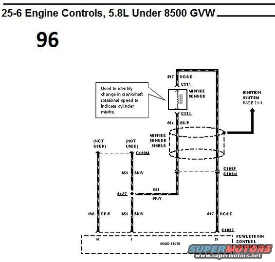
Engine controls wiring diagram for 1996 Ford Bronco 5.8L showing misfire sensor and ignition system circuits.
Part of 1992-1996 Ford Bronco Wiring Diagrams
This document is page 96 of a wiring diagram set, section 25-6 'Engine Controls, 5.8L Under 8500 GVW.' It shows the misfire sensor circuit for the 5.8L engine. The misfire sensor, described in a callout as being 'used to identify change in crankshaft rotational speed to indicate cylinder misfire,' connects through connector C114. Circuit 917 (dark green/light green, DG/LG) runs from the sensor through connectors C101F/C101M and C1027 to pin 59 of the Powertrain Control Module (PCM, solid state). Circuit 651 (black/yellow, BK/Y) provides the sensor ground/shield path, passing through the misfire sensor shield (shown as a dashed oval) and joining at splice S127 before reaching PCM pin 6 via connector C110M. Circuit 136 (dark blue/yellow, DB/Y) to PCM pin 84 is marked NOT USED, as is one 651 BK/Y branch. An arrow indicates the circuit also connects to the ignition system, referenced on page 21-1. A reader can learn the wire colors, circuit numbers, connector identifiers, splice location, and PCM pin assignments for the misfire sensor on this application.
Is this accurate? Sign in to help verify it.
Frequently asked questions
- What does the misfire sensor do according to this diagram?
- The callout states it is used to identify change in crankshaft rotational speed to indicate cylinder misfire.
- Which PCM pin does the misfire sensor signal wire (917 DG/LG) connect to?
- Circuit 917 DG/LG runs through connector C1027 to pin 59 of the Powertrain Control Module (PCM).
- What wire color and circuit number is the misfire sensor ground/shield wire?
- Circuit 651, black/yellow (BK/Y), which passes through the misfire sensor shield, joins at splice S127, and goes to PCM pin 6 via connector C110M.
- Which connectors are in the misfire sensor circuit?
- C114 (at the sensor), C101F/C101M, C110M, and C1027 at the PCM. Splice S127 is also shown.
- Are any wires in this diagram marked as not used?
- Yes. Circuit 136 DB/Y to PCM pin 84 and one 651 BK/Y branch are both labeled (NOT USED).
Comments
More from this build














No comments yet.