Home/
Registry/
Ford/
Bronco/
1992-1996/
“The Sleeper”/
Photo
supermotors.net/registry/media/1115731
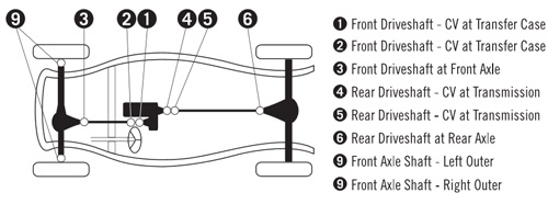
Ford Bronco U-Joint & CV Joint Location Diagram - Driveshaft & Axle Shaft
Reference · 1992-1996 BroncoAll 169 exploded parts diagrams
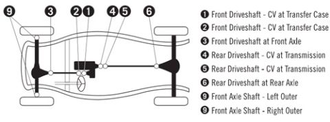

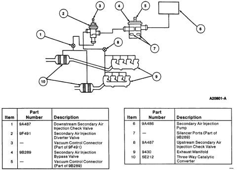
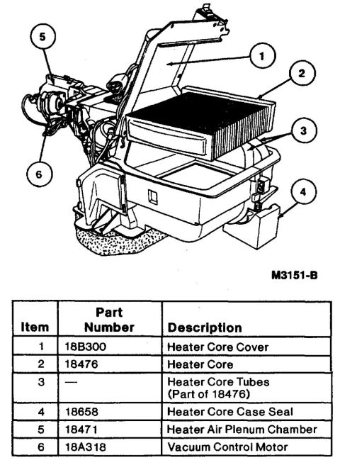
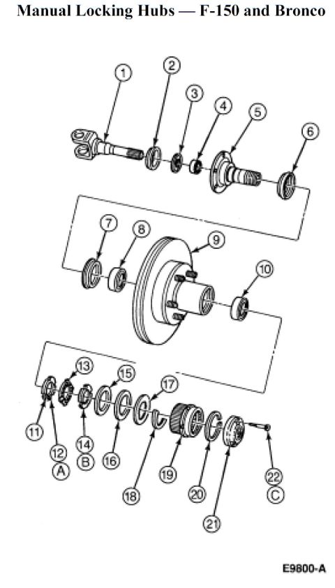








Component-identification diagram showing front/rear driveshafts, CV joints at transfer case and axle, and front axle shafts with a numbered legend.
Part of 1992-1996 Ford Bronco Exploded Parts Diagrams
This document is a labeled overhead diagram of a four-wheel-drive truck's driveline, identifying the locations of universal joints and CV (constant velocity) joints along the front and rear driveshafts and front axle shafts. Numbered callouts (1 through 9) point to specific joint positions on a schematic chassis illustration, and a legend to the right defines each: positions 1 and 2 are the front driveshaft CV joints at the transfer case, position 3 is the front driveshaft joint at the front axle, positions 4 and 5 are the rear driveshaft CV joints at the transmission, position 6 is the rear driveshaft joint at the rear axle, position 7 is the front axle shaft left outer joint, and positions 8 and 9 are labeled as front axle shaft right outer joints. The diagram helps an owner or mechanic identify which U-joint or CV joint they need to inspect or replace based on its physical location in the drivetrain. The document contains no part numbers, torque specifications, year, make, or model identification; it was uploaded to a 1996 Ford Bronco gallery. It functions as a quick-reference joint location map rather than a detailed service procedure.
Is this accurate? Sign in to help verify it.
Frequently asked questions
- Where are the front driveshaft CV joints located?
- According to the diagram, positions 1 and 2 are the front driveshaft CV joints at the transfer case, and position 3 is the front driveshaft joint at the front axle.
- Where are the rear driveshaft joints located?
- Positions 4 and 5 are the rear driveshaft CV joints at the transmission end, and position 6 is the rear driveshaft joint at the rear axle.
- What joints are on the front axle shafts?
- The legend identifies position 7 as the front axle shaft left outer joint, and positions 8 and 9 as front axle shaft right outer joints.
- Does this diagram include part numbers or torque specs?
- No. It is a location-only diagram identifying nine U-joint/CV joint positions on the driveline; no part numbers, sizes, or torque values are shown.






No comments yet.