Ford Bronco Manual Locking Hub Exploded Diagram - Part Numbers & Torque Specs
Reference · 1992-1996 BroncoAll 169 exploded parts diagrams










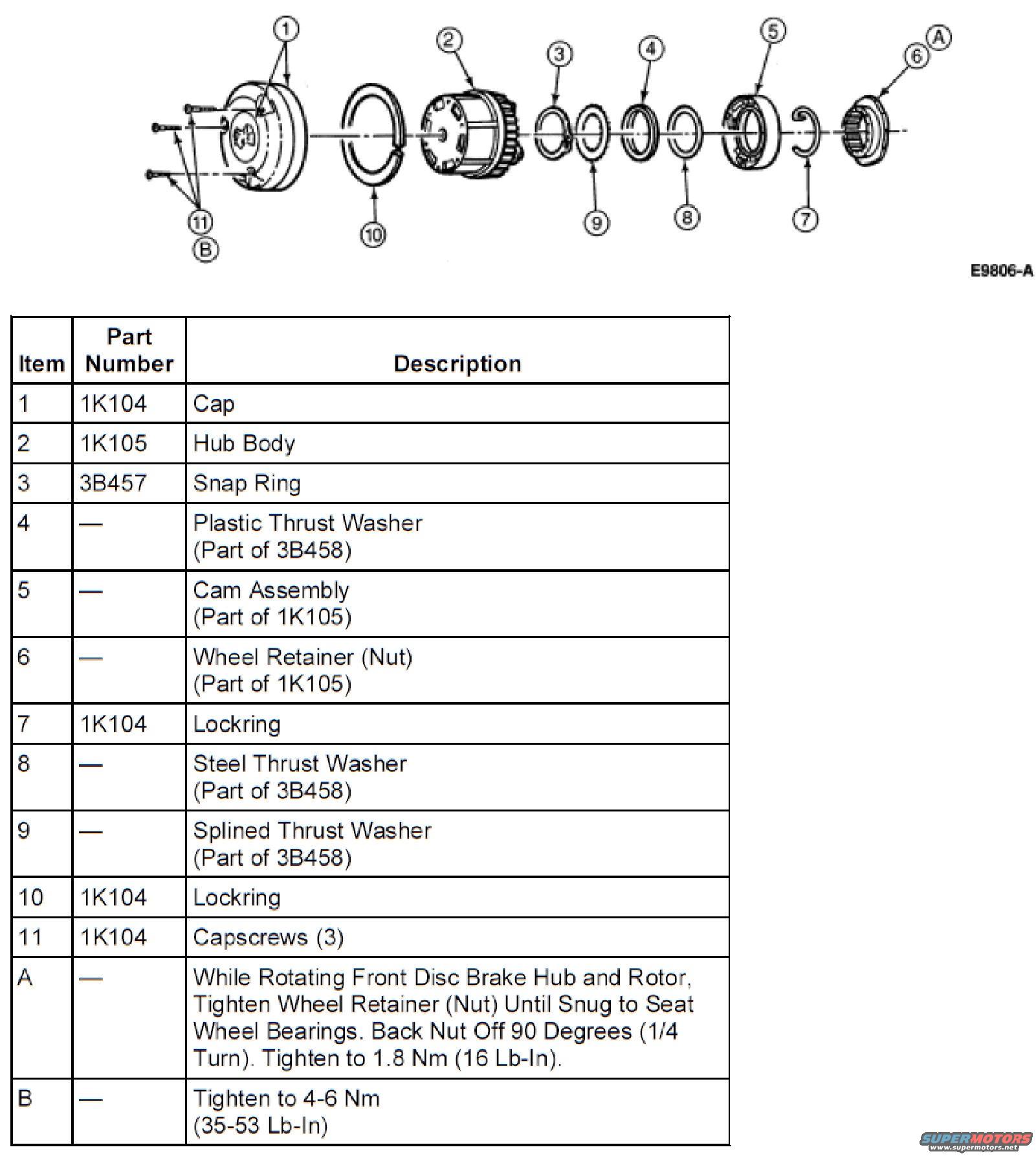
Exploded parts diagram of the automatic locking hub with a numbered part-number/description table and torque specifications.
Part of 1992-1996 Ford Bronco Exploded Parts Diagrams
This document is an exploded parts diagram (figure ID E9806-A) of a front manual locking hub assembly, uploaded as reference material for a 1995 Ford Bronco. The illustration shows the hub components arranged along an axis in disassembly order, each identified by a numbered or lettered callout. An accompanying table lists each item, its Ford base part number where applicable, and a description: cap (1K104), hub body (1K105), snap ring (3B457), plastic thrust washer (part of 3B458), cam assembly (part of 1K105), wheel retainer nut (part of 1K105), two lockrings (1K104), steel and splined thrust washers (part of 3B458), and three capscrews (1K104). Two torque/procedure notes are included: item A instructs that while rotating the front disc brake hub and rotor, the wheel retainer (nut) should be tightened until snug to seat the wheel bearings, backed off 90 degrees (1/4 turn), then tightened to 1.8 Nm (16 lb-in); item B specifies tightening the capscrews to 4-6 Nm (35-53 lb-in). The document is useful for identifying hub component order during disassembly/reassembly and for setting correct wheel bearing preload and cap screw torque values.
Is this accurate? Sign in to help verify it.
Frequently asked questions
- What torque should the wheel retainer nut be set to on the front locking hub?
- While rotating the front disc brake hub and rotor, tighten the wheel retainer (nut) until snug to seat the wheel bearings, back the nut off 90 degrees (1/4 turn), then tighten to 1.8 Nm (16 lb-in).
- What is the torque spec for the hub capscrews?
- The three capscrews (item 11, part of 1K104) are tightened to 4-6 Nm (35-53 lb-in).
- What part number is the hub body?
- The hub body (item 2) is part number 1K105.
- Which components are part of the 3B458 thrust washer set?
- The plastic thrust washer (item 4), steel thrust washer (item 8), and splined thrust washer (item 9) are all part of 3B458.
- What part number covers the cap, lockrings, and capscrews?
- Part number 1K104 covers the cap (item 1), the lockrings (items 7 and 10), and the three capscrews (item 11).






No comments yet.