1995 Ford Bronco Heater Core & Plenum Exploded Parts Diagram with Part Numbers

Reference · 1992-1996 BroncoAll 169 exploded parts diagrams
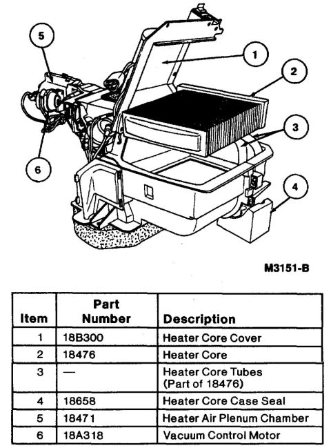










Exploded view of a Ford heater core assembly (M3151-B) identifying the heater core 18476, cover 18B300, case seal 18658, plenum 18471 and vacuum control motor 18A318.
Part of 1992-1996 Ford Bronco Exploded Parts Diagrams
This document is an exploded parts diagram (illustration reference M3151-B) showing the heater core assembly and related climate-control components, uploaded to a 1995 Ford Bronco's document gallery. The line drawing depicts the heater air plenum chamber with the heater core cover opened, revealing the heater core seated in its case, along with the heater core tubes, case seal, and the vacuum control motor mounted on the side of the plenum. Six numbered callouts on the illustration correspond to a legend table beneath it. The table lists each item with its Ford base part number and description: item 1 is the Heater Core Cover (18B300), item 2 is the Heater Core (18476), item 3 is the Heater Core Tubes (which are part of 18476 and have no separate number), item 4 is the Heater Core Case Seal (18658), item 5 is the Heater Air Plenum Chamber (18471), and item 6 is the Vacuum Control Motor (18A318). A reader can use this document to identify the components involved in heater core replacement, understand how the parts fit together within the plenum assembly, and obtain the base part numbers needed for ordering replacement parts. The document itself does not state a year, model, or engine applicability.
Is this accurate? Sign in to help verify it.
Frequently asked questions
- What is the Ford part number for the heater core in this diagram?
- The heater core is item 2, part number 18476. The heater core tubes (item 3) are part of 18476 and have no separate part number.
- What part number is the heater core cover?
- The heater core cover is item 1, part number 18B300.
- What components are shown in this exploded heater assembly diagram?
- Six items: Heater Core Cover (18B300), Heater Core (18476), Heater Core Tubes (part of 18476), Heater Core Case Seal (18658), Heater Air Plenum Chamber (18471), and Vacuum Control Motor (18A318).
- What part number is the vacuum control motor on the heater plenum?
- The vacuum control motor is item 6, part number 18A318.
- Is there a separate part number for the heater core tubes?
- No: the diagram's legend shows the heater core tubes (item 3) are part of the heater core assembly, part number 18476.






No comments yet.