Home/
Registry/
Ford/
Bronco/
1992-1996/
“Eddie Bauer”/
Photo
supermotors.net/registry/media/1069085
1994 Ford Bronco Parking Brake Cable Diagram - E-Brake Routing & Exploded Views
Reference · 1992-1996 BroncoAll 169 exploded parts diagrams

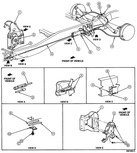
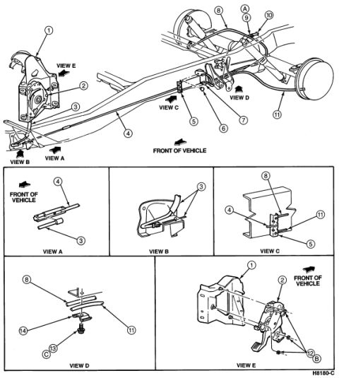
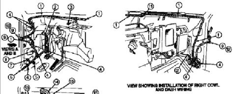
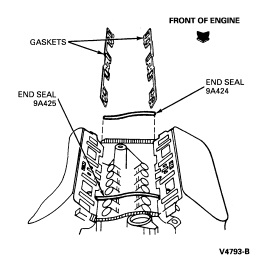
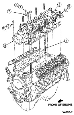












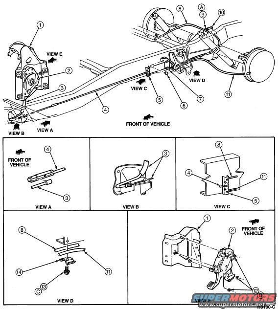
Exploded assembly diagram of parking-brake cable routing with numbered callouts and detail views A through E.
Part of 1992-1996 Ford Bronco Exploded Parts Diagrams
This document is an exploded parts / routing diagram (reference number H8180-C) showing the parking brake (emergency brake) cable system on a Ford truck chassis, uploaded as applying to a 1994 Ford Bronco. The main illustration shows the vehicle frame from underneath with the parking brake control assembly at the front, the front cable, an intermediate cable and equalizer/connector at mid-frame, and rear cables routing to both rear brake drums. Numbered callouts 1 through 14 identify individual components, and directional arrows labeled 'FRONT OF VEHICLE' establish orientation. Five detail insets (VIEW A through VIEW E) enlarge specific areas: VIEW A shows cable clip/retainer details (callouts 3, 4); VIEW B shows a cable bracket at the frame (callout 3); VIEW C shows the cable connector and bracket at the frame crossmember (callouts 4, 5, 8, 11); VIEW D shows the equalizer, clip, and fastener detail (callouts 8, 11, 13, 14); and VIEW E shows the parking brake pedal control assembly and mounting bracket with fasteners (callouts 1, 2). No legend, part numbers, torque values, or year/model text appears on this page, it is likely one page of a multi-page set whose legend is on a companion page.
Is this accurate? Sign in to help verify it.
Frequently asked questions
- What does this diagram show?
- It shows the routing and components of the parking brake (emergency brake) cable system on the vehicle's frame, with numbered callouts 1-14 and five enlarged detail views (VIEW A through VIEW E).
- Where is the parking brake control assembly shown?
- VIEW E shows the parking brake control (pedal) assembly and its mounting bracket, callouts 1 and 2, with an arrow indicating FRONT OF VEHICLE.
- What do the detail views cover?
- VIEW A shows front cable clips (callouts 3, 4); VIEW B shows a frame bracket (callout 3); VIEW C shows a cable connection at the frame crossmember (callouts 4, 5, 8, 11); VIEW D shows the equalizer/clip and fastener (callouts 8, 11, 13, 14); VIEW E shows the pedal control assembly (callouts 1, 2).
- Does the diagram list part numbers or torque specs?
- No. Only numbered/lettered callouts and the drawing reference H8180-C appear; there is no legend, part numbers, or torque values on this page.






No comments yet.