Ford Bronco Secondary Air Injection System Diagram - Thermactor Parts & Numbers

Reference · 1992-1996 BroncoAll 169 exploded parts diagrams
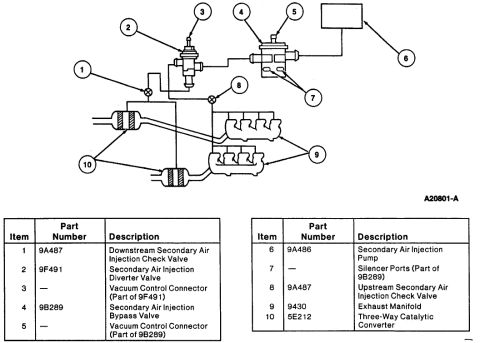
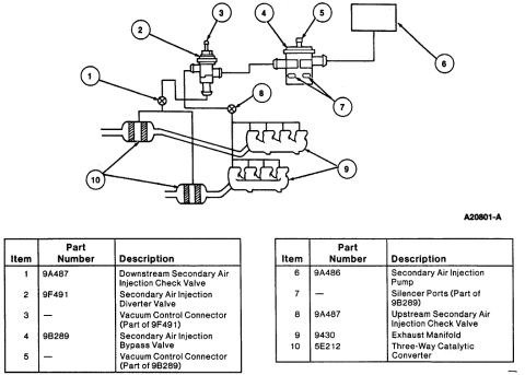







Secondary air injection (smog pump) system diagram (A20801-A) identifying check valves 9A487, diverter valve 9F491, bypass valve 9B289, pump 9A486, manifold 9430 and catalyst 5E212.
Part of 1992-1996 Ford Bronco Exploded Parts Diagrams
This document is an exploded/schematic parts diagram of a Ford Secondary Air Injection (Thermactor) system, identified by figure number A20801-A. The illustration shows the routing of air injection plumbing from the secondary air injection pump through the bypass and diverter valves, upstream and downstream check valves, and into the exhaust manifolds and three-way catalytic converters. Ten numbered callouts on the diagram correspond to two legend tables listing each component's item number, Ford base part number, and description. Components identified include the Downstream Secondary Air Injection Check Valve (9A487), Secondary Air Injection Diverter Valve (9F491), Vacuum Control Connector (part of 9F491), Secondary Air Injection Bypass Valve (9B289), Vacuum Control Connector (part of 9B289), Secondary Air Injection Pump (9A486), Silencer Ports (part of 9B289), Upstream Secondary Air Injection Check Valve (9A487), Exhaust Manifold (9430), and Three-Way Catalytic Converter (5E212). A reader can use this document to identify the location, connection order, and Ford base part numbers of the secondary air injection (smog pump) system components, useful when diagnosing emissions faults or ordering replacement parts. The document itself does not state a year, model, or engine applicability.
Is this accurate? Sign in to help verify it.
Frequently asked questions
- What part number is the Secondary Air Injection Pump?
- The Secondary Air Injection Pump is item 6, Ford base part number 9A486.
- What are the check valve part numbers in the secondary air injection system?
- Both the Downstream Secondary Air Injection Check Valve (item 1) and the Upstream Secondary Air Injection Check Valve (item 8) are part number 9A487.
- What is the part number for the Secondary Air Injection Diverter Valve and Bypass Valve?
- The Diverter Valve is 9F491 (item 2) and the Bypass Valve is 9B289 (item 4). Each has an integral Vacuum Control Connector, and the Silencer Ports (item 7) are part of the 9B289 bypass valve.
- What part number is the three-way catalytic converter shown in this diagram?
- The Three-Way Catalytic Converter is item 10, part number 5E212; the Exhaust Manifold is item 9, part number 9430.






No comments yet.