SuperMotors SuperMotors SUPERMOTORS Search: try “orange Bronco on 35s”
Home/ Registry/ Ford/ Bronco/ 1992-1996/ “JUICE”/ Photo supermotors.net/registry/media/1055179

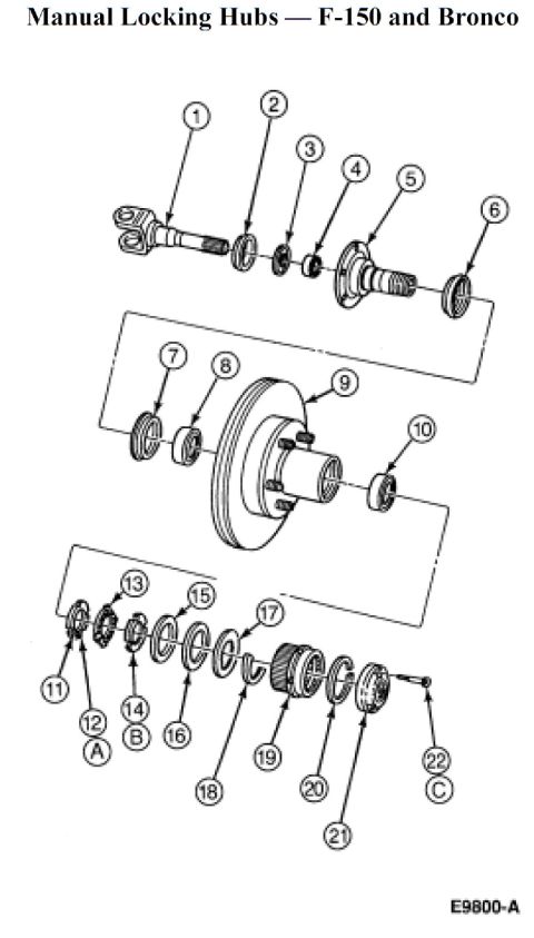
Ford F-150 & Bronco Manual Locking Hub Exploded Diagram - Front Hub Assembly
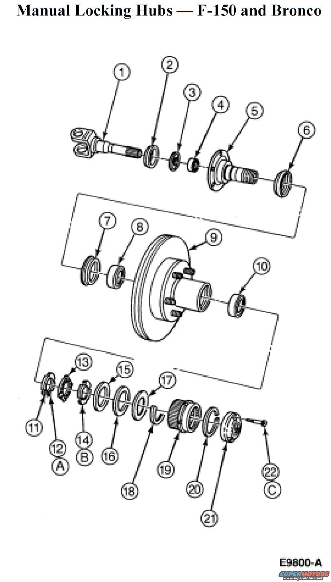
Exploded view of F-150/Bronco manual locking hub assembly with numbered callouts
Exploded view of F-150/Bronco manual locking hub assembly with numbered calloutsOriginal file
Exploded view of F-150/Bronco manual locking hub assembly with numbered callouts

Reference · 1992-1996 BroncoAll 169 exploded parts diagrams
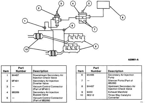
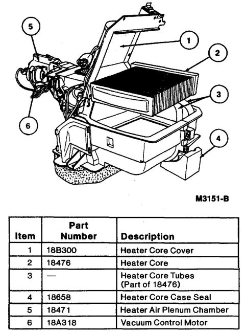
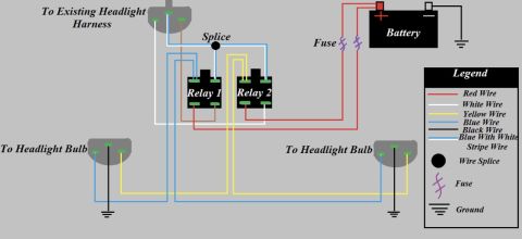
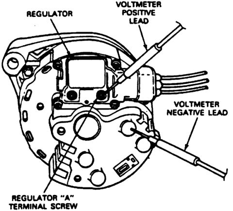
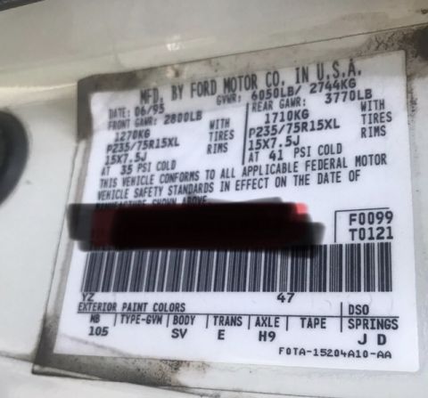
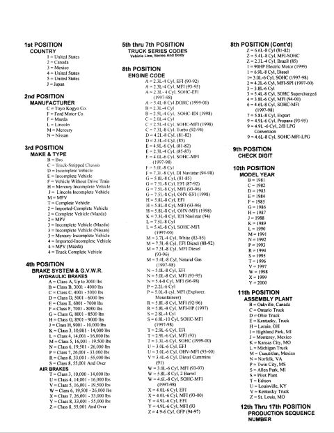
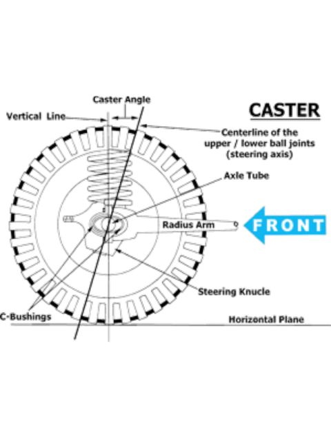
Ford Bronco Secondary Air Injection System Diagram - Smog Pump Parts & Layout Ford Bronco Secondary Air Injection System Diagram - Thermactor Parts & Numbers 1995 Ford Bronco Heater Core & Plenum Exploded Parts Diagram with Part Numbers Ford F-150 & Bronco Manual Locking Hub Exploded Diagram - Front Hub Assembly Ford Bronco Manual Locking Hub Exploded Diagram - Part Numbers & Torque Specs Ford F-150 & Bronco Automatic Locking Hub Exploded Diagram (E9804-A) Ford Bronco Front Wheel Bearing & Hub Exploded Diagram with Torque Specs Ford Bronco/F-150 4x4 Front Hub & Wheel Bearing Exploded Diagram w/ Torque Specs 1996 Ford Bronco/F-150 Distributor Exploded Parts Diagram & Installation 03-07A-6 Ford Bronco Front Coil Spring & Shock Absorber Exploded Diagram (F2858-Q) Ford Bronco/F-Series Engine Block Ground Cable Diagram - Neg Battery Cable Views Instrument panel 04320 exploded view with finish panel 044D70, headlamp switch knob 11666 and mouldings 169exploded parts diagrams1992-1996 Ford Bronco More reference Headlight Relay Wiring Diagram - Dual Relay Harness Upgrade (Ford Bronco)Wiring diagram Ford Alternator Voltage Regulator Test Diagram - Voltmeter Lead PlacementService procedure 1995 Ford Bronco Door Jamb Data Plate - GVWR, Tire Pressure & Axle CodesSpec plate Ford truck VIN decoder chart explaining positions 1 through 17, engine codes, model years and plantsManual page Caster Angle Diagram - Ford Solid Axle Radius Arm & C-Bushing Steering GeometrySchematic Line graph of percentage change in Bronco values, 2008 to 2018, for four Ford Bronco generationsBrochure Ford Bronco A/C-Heater Vacuum Diagram - HVAC Vacuum Line Routing & Door MotorsVacuum routing Brake Booster to Master Cylinder Adapter Plate Blueprint - Ford Bronco SwapBlueprint Ford Bronco/F-Series Fuse 18 (10A) - Speedometer, Air Bag, Shift ControlFuse chart Rod Bolt Stretch Monitoring Chart - 8-Rod V8 Connecting Rod Bolt Record SheetTorque spec

Exploded parts diagram of the F-150 and Bronco manual locking hub, spindle, and bearing assembly with numbered callouts.

Part of 1992-1996 Ford Bronco Exploded Parts Diagrams

AI caption · Photo 91 of 561

This document is a single-page exploded parts diagram titled "Manual Locking Hubs: F-150 and Bronco." It illustrates the complete front hub, spindle, and manual locking hub assembly for Ford F-150 and Bronco 4x4 trucks. The drawing shows the front axle shaft and stub/joint assembly, spindle with bearing and seal components, the rotor/hub assembly with wheel studs, inner and outer wheel bearings, seals, and the full stack-up of the manual locking hub mechanism, including snap rings, washers, lock rings, the hub body, and the outer hub dial/cap secured by a small fastener. Twenty-two numbered callouts (1 through 22) identify individual parts in assembly order, and three lettered callouts (A at item 12, B at item 14, C at item 22) appear to flag special steps or notes; however, no legend, part names, part numbers, or torque specifications are printed on this page, the key presumably appears on an accompanying page. The Ford illustration reference code E9800-A appears at the bottom right. A reader can use this diagram to understand the disassembly/reassembly order of the front hub and manual locking hub components on these vehicles.

Is this accurate? Sign in to help verify it.

Frequently asked questions

What does this diagram show?
An exploded view of the manual locking hub and front hub/spindle assembly for the Ford F-150 and Bronco, with parts identified by numbered callouts 1 through 22.
Does the diagram include a parts legend or part names?
No. Only the numbered callouts (1-22), lettered markers A, B, and C, and the illustration code E9800-A are shown; the legend identifying each number is not on this page.
Which vehicles does this diagram apply to?
The title states it covers the Ford F-150 and Bronco with manual locking hubs.
How many components are called out in the exploded view?
Twenty-two numbered components are called out, with letters A, B, and C attached to items 12, 14, and 22 respectively.


Comments

No comments yet.

More 1992-1996 Broncos