Home/
Registry/
Ford/
Bronco/
1992-1996/
“Buckin Bronco”/
Photo
supermotors.net/registry/media/1136376
Ford Backup Lamp Wiring Diagram 93-1 - Reverse Light Circuit, C6 & Manual Trans
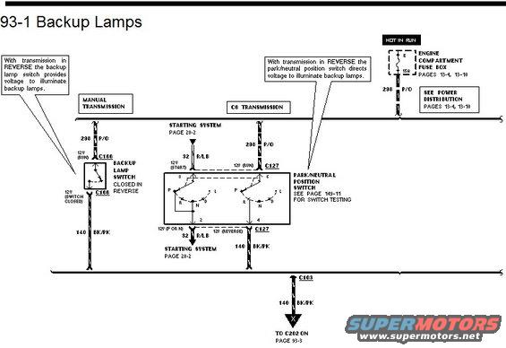
Backup lamp wiring diagram showing the manual transmission backup lamp switch and automatic park/neutral position switch circuits.
This is page 93-1, "Backup Lamps," from a Ford wiring diagram manual, showing the backup (reverse) lamp circuits for both manual and C6 automatic transmissions. Power comes from fuse E (15A) in the engine compartment fuse box (hot in run; see pages 13-4 and 13-10 for power distribution) via circuit 298 P/O (purple/orange). On manual transmission vehicles, the voltage passes through connector C166 to the backup lamp switch, which closes in reverse and feeds circuit 140 BK/PK (black/pink) to the lamps. On C6 automatic transmission vehicles, the voltage goes through connector C127 to the park/neutral position switch (switch testing on page 149-11), which routes voltage to circuit 140 BK/PK when in reverse; the same switch also interfaces with the starting system on circuit 32 R/LB (see page 20-2), providing 12V in park or neutral for starting. The 140 BK/PK output passes through connector C103 and continues to connector C202 on page 93-3. Callouts explain that with the transmission in reverse, either the backup lamp switch or the park/neutral position switch directs voltage to illuminate the backup lamps.
Is this accurate? Sign in to help verify it.
Frequently asked questions
- What fuse powers the backup lamps in this diagram?
- Fuse E, a 15A fuse in the engine compartment fuse box (hot in run), feeds the circuit via wire 298 P/O. Power distribution details are on pages 13-4 and 13-10.
- What wire color feeds the backup lamps after the switch?
- Circuit 140 BK/PK (black/pink) carries voltage from the backup lamp switch or park/neutral position switch to the backup lamps, passing through connector C103 to C202 on page 93-3.
- How do the backup lamps work with a manual transmission?
- With the transmission in reverse, the backup lamp switch (through connector C166) closes and provides voltage from wire 298 P/O to wire 140 BK/PK to illuminate the backup lamps.
- How do the backup lamps work with a C6 automatic transmission?
- The park/neutral position switch, connected through connector C127, directs 12V from wire 298 P/O to wire 140 BK/PK when the transmission is in reverse. Switch testing is on page 149-11.
- What circuit connects the park/neutral position switch to the starting system?
- Circuit 32 R/LB connects the park/neutral position switch to the starting system (page 20-2), carrying 12V in start and 12V when in Park or Neutral.
Comments
More from this build














No comments yet.