SuperMotors SuperMotors SUPERMOTORS Search: try “orange Bronco on 35s”
Home/ Registry/ Ford/ Bronco/ 1992-1996/ “Buckin Bronco”/ Photo supermotors.net/registry/media/1122372

Ford 5.0L wiring diagram of heated oxygen sensors HO2S #11 and #…
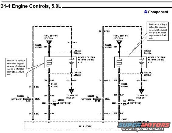
Ford factory wiring schematic page headed "24-4 Engine Controls, 5.0L," showing the heated oxygen sensor circuits HO2S #11 and #21 with their heater elements and signal wires running to the powertrain control module. Callout boxes on both sides state the sensor provides a voltage related to exhaust gas oxygen content for air/fuel ratio regulation.

AI caption · Photo 310 of 378

Is this accurate? Sign in to help verify it.

Comments

No comments yet.

More from this build

Ford 5.8L California engine controls wiring diagram page 25-12, inertia fuel shutoff and fuel pump module Ford 5.8L California engine controls wiring diagram page 25-11, malfunction indicator lamp and HO2S Ford 5.8L California engine controls wiring diagram page 25-10, IAT sensor and heated oxygen sensor Ford 5.8L California engine controls wiring diagram page 25-9, EGR, ECT, TP and EGR valve position sensors Ford 5.8L California engine controls wiring diagram page 25-8, fuel injectors and idle air control circuits Ford 5.8L California engine controls wiring diagram page 25-7, PCM power relay and fuel pump circuits Vehicle Speed Sensor (VSS) wiring diagram, Bronco, page 64-2, rear axle sensor and PSOM circuits Vehicle Speed Sensor (VSS) wiring diagram, F-Series, page 64-1, rear axle sensor and PSOM circuits

More 1992-1996 Broncos