Home/
Registry/
Ford/
Bronco/
1992-1996/
“Buckin Bronco”/
Photo
supermotors.net/registry/media/1122375
Ford 5.0L wiring diagram of malfunction indicator lamp, ignition…
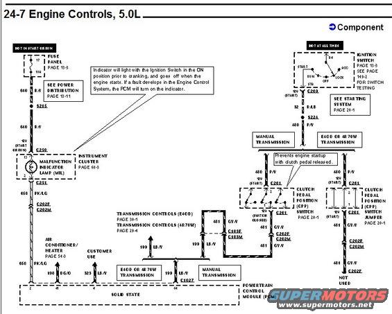
Ford factory wiring schematic page headed "24-7 Engine Controls, 5.0L," showing the malfunction indicator lamp (MIL) circuit in the instrument cluster, the ignition switch and starting system feeds, and clutch pedal position (CPP) switch branches for manual versus E4OD/4R70W transmissions, all tied to the powertrain control module. Callouts explain MIL behavior at key-on and that the CPP switch prevents engine startup with the clutch pedal released.
Is this accurate? Sign in to help verify it.
Comments
More from this build














No comments yet.