Home/
Registry/
Ford/
Bronco/
1992-1996/
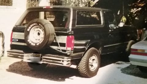
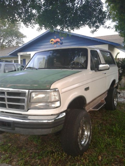
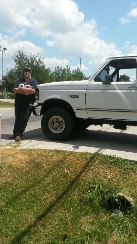
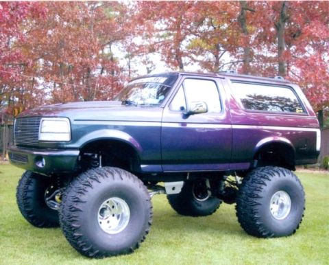
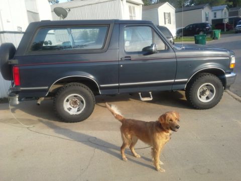
“Buckin Bronco”/
Photo
supermotors.net/registry/media/1136397
1996 Ford Bronco C107 & C109 In-Line Connector Pinout - Wire Colors & Circuits

Electrical connector pinout diagrams for in-line connectors C107 and C109 showing terminal numbering and wire color assignments.
This document is a wiring connector pinout reference page showing two in-line connectors, C107 and C109, each depicted from both mating faces (female and male views). For C107, the female side (C107F) belongs to harness 12A690 and the male side (C107M) to harness 12A581. It is an 8-cavity round connector; populated circuits are 74 (GY/LB), 387 (R/W), 361 (R), 359 (GY/R), 514 (Y/R), and 516 (Y/BK), with pins 5 and 6 shown filled (unused/blocked). For C109, the female side (C109F) is on harness 15525 and the male side (C109M) on harness 12A581, also an 8-cavity round connector carrying circuits 359 (GY/R), 361 (R), 388 (Y/LB), 94 (R/BK), 389 (W/BK), 651 (BK/Y), 136 (DB/Y), and 392 (R/LG). Footnotes indicate circuits 651 and 136 apply only with the 4R70W transmission, and circuits 388 and 94 apply only with the 5.8L engine. A reader can use this page to identify pin positions, circuit numbers, and wire colors when diagnosing or repairing engine/transmission harness connections at these two in-line connectors.
Is this accurate? Sign in to help verify it.
Frequently asked questions
- What wire circuits are in connector C107?
- C107 carries circuits 74 (GY/LB), 387 (R/W), 361 (R), 359 (GY/R), 514 (Y/R), and 516 (Y/BK). Pins 5 and 6 are shown filled/black (not populated with labeled circuits).
- What harnesses do C107F and C107M belong to?
- The female side C107F is part of harness 12A690, and the male side C107M is part of harness 12A581.
- What circuits are in connector C109 and which are engine/transmission specific?
- C109 carries circuits 359 (GY/R), 361 (R), 388 (Y/LB), 94 (R/BK), 389 (W/BK), 651 (BK/Y), 136 (DB/Y), and 392 (R/LG). Circuits 651 (BK/Y) and 136 (DB/Y) apply only with the 4R70W transmission, and circuits 388 (Y/LB) and 94 (R/BK) apply only with the 5.8L engine.
- What harness part numbers are shown on this page?
- Harness numbers 12A690 (C107 female side), 12A581 (C107 and C109 male sides), and 15525 (C109 female side).
- How many pins do connectors C107 and C109 have?
- Both C107 and C109 are shown as 8-cavity in-line connectors, numbered 1-8 in two rows of four.
Comments
More from this build








No comments yet.