Home/
Registry/
Ford/
Bronco/
1992-1996/
“Buckin Bronco”/
Photo
supermotors.net/registry/media/1137647
Ford 4.9L Engine Controls Wiring Diagram 23-5 - PCM, ECT, IAT & Knock Sensor
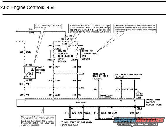
Ford 4.9L engine controls wiring diagram showing knock sensor, ECT, IAT and vehicle speed sensor circuits with color-coded wires.
This document is page 23-5 of a Ford factory wiring diagram covering Engine Controls for the 4.9L engine. It shows the sensor input side of the Powertrain Control Module (PCM), including the Knock Sensor (KS) at connector C1009 (circuit 310 Y/R to PCM pin 23), the Engine Coolant Temperature (ECT) sensor at connector C183 (circuit 354 LG/R to PCM pin 7), and the Intake Air Temperature (IAT) sensor at connector C164 (circuit 743 GY to PCM pin 25). Both temperature sensors share sensor signal return/reference circuit 359 GY/R through splice S138 and connector C125. Callout notes explain each sensor's function: the knock sensor detects engine detonation (spark knock), while the ECT and IAT are thermistors whose resistance decreases with temperature, used by the PCM for idle speed, fuel delivery, spark timing and EGR control. Additional PCM inputs shown include the brake pedal signal (circuit 511 LG, 12V with pedal depressed) from the Turn/Stop/Hazard Lamps circuit (page 90-2), and A/C-heater inputs (883 PK/LB and 348 P) from page 54-2. PCM outputs at the bottom connect to the Vehicle Speed Sensor (676 PK/O, 679 GY/BK; pages 64-1, 64-2) and the VIP data link connectors (915 PK/LB, 914 T/O, 209 W/P via C198/C199).
Is this accurate? Sign in to help verify it.
Frequently asked questions
- What wire color is the knock sensor signal on the 4.9L engine?
- The knock sensor (KS) at connector C1009 uses circuit 310, wire color Y/R (yellow/red), which runs to PCM pin 23. The sensor return side uses circuit 359 GY/R.
- Which PCM pin does the ECT sensor connect to?
- The Engine Coolant Temperature (ECT) sensor at connector C183 connects through circuit 354 LG/R (via connectors C125 and C101) to PCM pin 7; its other lead is circuit 359 GY/R.
- What is the IAT sensor circuit on the 4.9L?
- The Intake Air Temperature (IAT) sensor at connector C164 uses circuit 743 GY to PCM pin 25 and shares circuit 359 GY/R with the ECT sensor via splice S138.
- How do the ECT and IAT sensors work according to this diagram?
- Both are thermistors whose resistance decreases as temperature increases. The PCM detects the voltage drop and uses it to calculate idle speed, fuel delivery, spark timing and EGR control.
- Which circuits connect the PCM to the Vehicle Speed Sensor?
- The Vehicle Speed Sensor (VSS) connects via circuit 676 PK/O to PCM pin 6 and circuit 679 GY/BK to PCM pin 3; further detail is on pages 64-1 and 64-2.
Comments
More from this build














No comments yet.