Home/
Registry/
Ford/
Bronco/
1992-1996/
“Buckin Bronco”/
Photo
supermotors.net/registry/media/1137661
Ford 5.8L Engine Controls Wiring Diagram 25-4 - MAP Sensor, HO2S, PCM (Bronco)
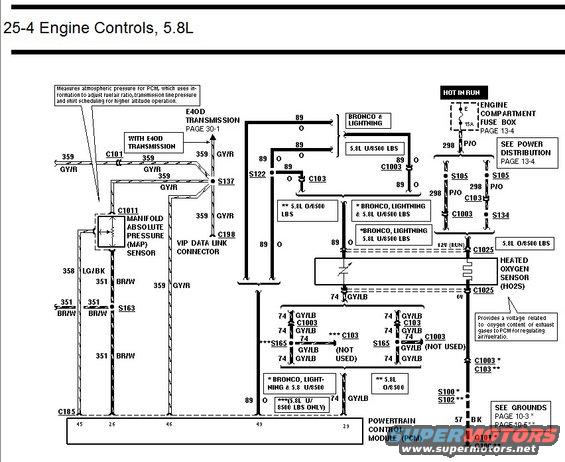
Ford 5.8L engine controls wiring diagram of MAP sensor and heated oxygen sensor circuits for Bronco and Lightning applications.
This document is page 25-4 of a Ford factory-style wiring diagram set covering Engine Controls for the 5.8L engine. It shows the wiring for the Manifold Absolute Pressure (MAP) sensor (connector C1011), the VIP Data Link Connector (C198), and the Heated Oxygen Sensor (HO2S, connector C1025), all terminating at the Powertrain Control Module (PCM) at connector C185 (pins 45, 26, 46, 49, and 29). Power for the HO2S heater comes from a 15A fuse in the Engine Compartment Fuse Box (Hot in Run, see Power Distribution page 13-4) via circuit 298 (P/O). Key circuits include 359 GY/R (MAP/reference), 89 O, 358 LG/BK, 351 BR/W, 74 GY/LB (signal return), and ground circuit 57 BK to grounds G101/G100 (see Grounds pages 10-3/10-5). Splices and connectors shown include S137, S122, S163, S165, S105, S134, C101, C103, C1003, S100, S102. Notes distinguish applications: Bronco & Lightning, 5.8L under 8500 lbs GVW, and 5.8L over 8500 lbs. Callouts explain that the MAP sensor measures atmospheric pressure for fuel ratio, transmission line pressure, and shift scheduling, and that the HO2S provides a voltage related to exhaust oxygen content. A cross-reference points to E4OD transmission wiring on page 30-1.
Is this accurate? Sign in to help verify it.
Frequently asked questions
- What does the MAP sensor do according to this diagram?
- It measures atmospheric pressure for the PCM, which uses the information to adjust fuel/air ratio, transmission line pressure, and shift scheduling for higher altitude operation.
- What fuse powers the heated oxygen sensor circuit?
- A 15A fuse in the Engine Compartment Fuse Box on a Hot in Run circuit, feeding circuit 298 (P/O wire); see Power Distribution page 13-4.
- What wire colors are used for the MAP sensor circuits?
- Circuit 359 is GY/R (gray/red), circuit 358 is LG/BK (light green/black), and circuit 351 is BR/W (brown/white).
- What is the signal return wire for the oxygen sensor and other sensors?
- Circuit 74, a GY/LB (gray/light blue) wire, which connects through splices S165 and connectors C1003/C103 to PCM pin 49.
- Where does the ground circuit for this system go?
- Circuit 57 (BK) goes to grounds G101 (via S100) or G100 (via S102) depending on application; see Grounds pages 10-3 and 10-5.
Comments
More from this build














No comments yet.