Home/
Registry/
Ford/
Bronco/
1992-1996/
“Buckin Bronco”/
Photo
supermotors.net/registry/media/1137660
Ford Bronco 5.8L Engine Controls Wiring Diagram - PCM, TPS, ECT, IAT, EGR Sensors
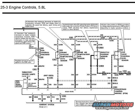
Ford 5.8L engine controls wiring diagram showing EGR control solenoid, ECT, IAT, throttle position and EGR valve position sensor circuits.
This document is page 25-3 of a Ford factory-style wiring diagram set, covering the Engine Controls system for the 5.8L engine. It shows the Powertrain Control Module (PCM, labeled solid state) and its connections to five engine sensors/actuators: the EGR Control Solenoid (connector C180), Engine Coolant Temperature (ECT) sensor (C183), Intake Air Temperature (IAT) sensor (C164), Throttle Position Sensor (TPS, connector C1024), and EGR Valve Position (EVP) sensor (C182). Explanatory callouts describe each component's function, the ECT and IAT are thermistors whose resistance decreases with temperature, the TPS is a potentiometer indicating throttle plate angle, and the EVP reports EGR valve position to the PCM. Wire circuits and colors are labeled, including 361 R, 359 GY/R (sensor signal return, splice S161), 360 BR/PK, 511 LG, 310 Y/R, 354 LG/R (ECT), 743 GY (IAT), 355 GY/W (TPS), 351 BR/W (EVP, splice S135), 352 BR/LG, plus 382 Y/BK, 259 O/R, 929 PK, and 395 GY/O feeding the ignition system. PCM connector pins 2, 33, 23, 7, 25, 47, 27, 4, 16, 36, and 56 are identified. Cross-references point to Turn/Stop/Hazard Lamps (page 90-2) and Ignition System (page 21-1), with a note for E4OD transmission applications.
Is this accurate? Sign in to help verify it.
Frequently asked questions
- What connector is used for the Throttle Position Sensor (TPS) on the 5.8L?
- The TPS connects through connector C1024, with signal wire 355 GY/W to PCM pin 47 and shared 359 GY/R sensor return.
- What wire color is the ECT sensor signal on the 5.8L engine controls circuit?
- The Engine Coolant Temperature sensor signal is circuit 354 LG/R (light green/red) through connector C183 to PCM pin 7.
- What does the EGR Control Solenoid do according to this diagram?
- It regulates the amount of vacuum applied to the EGR valve and is fed 12V when the relay is energized, with circuit 360 BR/PK to the PCM through connector C180.
- How do the ECT and IAT sensors work per the diagram callouts?
- Both are thermistors whose resistance decreases as temperature increases; the PCM detects voltage drops and uses the information to calculate fuel delivery, spark timing, idle speed and EGR control.
- Which PCM pins are shown for the engine control sensors?
- Pins shown include 2, 33, 23, 7 (ECT 354 LG/R), 25 (IAT 743 GY), 47 (TPS 355 GY/W), and 27 (EVP 352 BR/LG), plus pins 4, 16, 36 and 56 going to the ignition system (382 Y/BK, 259 O/R, 929 PK, 395 GY/O).
Comments
More from this build














No comments yet.