MaxTow Water Temperature Gauge Install Instructions MT-DV06 MT-WDV06 (Page 1)
Reference · 1992-1996 BroncoAll 143 service procedures






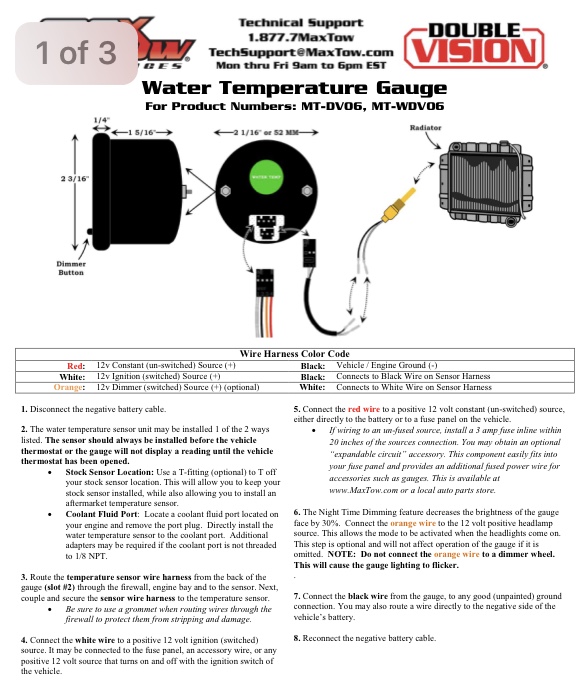
Gauge installation instruction sheet with wiring color-code table, gauge diagram, and numbered install steps.
Part of 1992-1996 Ford Bronco Service Procedures
This document is page 1 of 3 of the installation instructions for the MaxTow Double Vision Water Temperature Gauge, product numbers MT-DV06 and MT-WDV06. It includes a dimensioned diagram of the 2 1/16" (52 mm) gauge showing its 1/4" bezel depth, 1 5/16" body depth, 2 3/16" height, dimmer button location, and the temperature sensor connection at the radiator. A wire harness color code table defines the red wire as 12v constant power, white as 12v switched ignition power, orange as an optional 12v dimmer source, and black as ground, plus sensor harness connections. Eight numbered installation steps cover disconnecting the battery, installing the temperature sensor (either via a T-fitting at the stock sensor location or directly into a 1/8 NPT coolant port, always before the thermostat), routing the sensor harness through the firewall with a grommet, wiring the white, red, orange, and black wires, installing a 3 amp inline fuse within 20 inches if using an un-fused source, and using the orange wire for a night-time dimming feature that reduces gauge brightness by 30% (with a warning not to connect it to a dimmer wheel). Technical support contact information (1.877.7MaxTow, [email protected]) is provided.
Is this accurate? Sign in to help verify it.
Frequently asked questions
- What wire colors does the MaxTow water temperature gauge use and what do they connect to?
- Red connects to a 12v constant (un-switched) source (+), white to a 12v ignition (switched) source (+), orange to an optional 12v dimmer (switched) source (+), and black to vehicle/engine ground (-). On the sensor harness, black connects to the black wire and white to the white wire.
- Where should the water temperature sensor be installed?
- It must be installed before the vehicle thermostat, either by using a T-fitting at the stock sensor location or by installing it directly into a coolant fluid port on the engine. Adapters may be needed if the port is not threaded to 1/8 NPT.
- What size is the gauge?
- The gauge is 2 1/16" (52 mm) in diameter, with a 1/4" bezel, 1 5/16" body depth, and 2 3/16" overall height per the diagram.
- What fuse is required if wiring the red wire to an un-fused source?
- Install a 3 amp fuse inline within 20 inches of the source connection.
- How does the night time dimming feature work?
- Connecting the orange wire to a 12 volt positive headlamp source decreases gauge face brightness by 30% when the headlights come on. It is optional, but do not connect the orange wire to a dimmer wheel or the gauge lighting will flicker.






No comments yet.