SuperMotors SuperMotors SUPERMOTORS Search: try “orange Bronco on 35s”
Home/ Registry/ Ford/ Bronco/ 1992-1996/ “JUICE”/ Photo supermotors.net/registry/media/832119

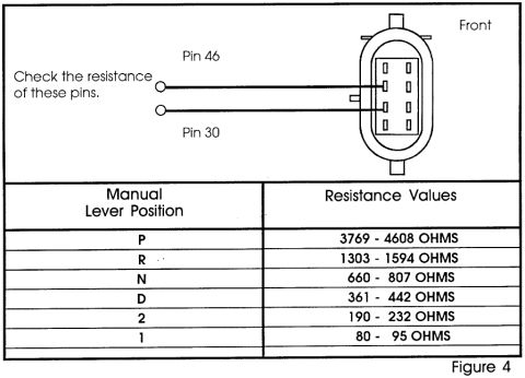
Ford MLP Sensor Resistance Chart - Pins 46 & 30 Test Values (1995 Bronco)

MLP sensor resistance test diagram with lever position spec table
MLP sensor resistance test diagram with lever position spec tableOriginal file
MLP sensor resistance test diagram with lever position spec table

Reference · 1992-1996 BroncoAll 143 service procedures
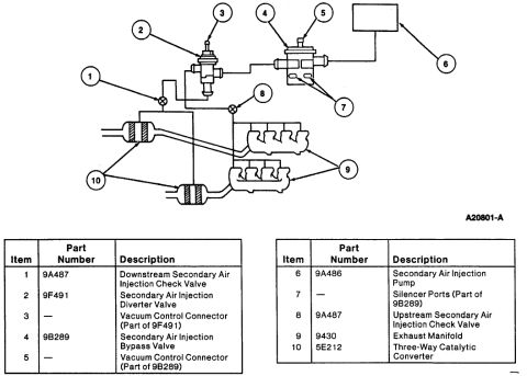
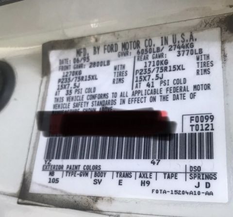
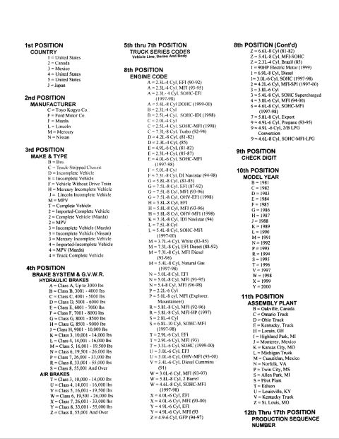
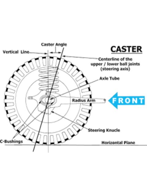
Test step B1 chart for speed control actuator and throttle body linkage MaxTow Double Vision Gauge Brightness Settings & Installation Requirements MaxTow Water Temperature Gauge Install Instructions MT-DV06 MT-WDV06 (Page 1) Ford Rear Axle Shaft & Wheel Bearing Retainer Key Diagram (3B459, 3B387) Ford Bronco Front Hub & Rotor Wheel Bearing Diagram - Service Illustration Ford Transmission Fluid Temperature Sensor Location Diagram - 1995 Bronco E4OD Ford MLP Sensor Resistance Chart - Pins 46 & 30 Test Values (1995 Bronco) Ford 5.8L Timing Chain & Sprocket Alignment Marks Diagram - 1995 Bronco Ford F150/F250/F350 4x4 & Bronco Truck Jacking Instructions Label E7TA-17A083-EA 1994 Ford Bronco/F-150/Econoline Anti-Theft Alarm Diagnosis Test M (13-11-22) 1994 Ford Bronco/F-150 Anti-Theft Alarm Diagnosis - Tests K & L (13-11-21) Parasitic Battery Draw Test Procedure - Checking for Unwanted Draw (Wilson) 143service procedures1992-1996 Ford Bronco More reference Headlight Relay Wiring Diagram - Dual Relay Harness Upgrade (Ford Bronco)Wiring diagram Ford Bronco Secondary Air Injection System Diagram - Smog Pump Parts & LayoutExploded parts 1995 Ford Bronco Door Jamb Data Plate - GVWR, Tire Pressure & Axle CodesSpec plate Ford truck VIN decoder chart explaining positions 1 through 17, engine codes, model years and plantsManual page Caster Angle Diagram - Ford Solid Axle Radius Arm & C-Bushing Steering GeometrySchematic Line graph of percentage change in Bronco values, 2008 to 2018, for four Ford Bronco generationsBrochure Ford Bronco A/C-Heater Vacuum Diagram - HVAC Vacuum Line Routing & Door MotorsVacuum routing Brake Booster to Master Cylinder Adapter Plate Blueprint - Ford Bronco SwapBlueprint Ford Bronco/F-Series Fuse 18 (10A) - Speedometer, Air Bag, Shift ControlFuse chart Rod Bolt Stretch Monitoring Chart - 8-Rod V8 Connecting Rod Bolt Record SheetTorque spec

Diagnostic figure to check MLP sensor resistance at pins 46 and 30 with a manual lever position resistance-value table.

Part of 1992-1996 Ford Bronco Service Procedures

AI caption · Photo 20 of 561

This document (labeled Figure 4) is a diagnostic reference for testing an automatic transmission's Manual Lever Position (MLP) sensor via its electrical connector. The top portion shows a diagram of the connector viewed from the front, with two test leads pointing to Pin 46 and Pin 30 and the instruction 'Check the resistance of these pins.' Below the diagram is a table listing the expected resistance values between those two pins for each manual lever (gear selector) position: Park (P) should read 3769-4608 ohms, Reverse (R) 1303-1594 ohms, Neutral (N) 660-807 ohms, Drive (D) 361-442 ohms, position 2 should read 190-232 ohms, and position 1 should read 80-95 ohms. A technician can use this chart with an ohmmeter to verify that the sensor's resistance changes correctly as the shift lever is moved through each position, helping diagnose shifting or starting problems related to a faulty or misadjusted sensor. The document itself contains no year, make, model, or part number information; it was uploaded to a 1995 Ford Bronco gallery as part of a transmission service document set.

Is this accurate? Sign in to help verify it.

Frequently asked questions

Which connector pins do I test for resistance?
The diagram instructs you to check the resistance between Pin 46 and Pin 30 of the connector, viewed from the front.
What resistance should the sensor read in Park?
With the manual lever in P (Park), the resistance between pins 46 and 30 should be 3769 - 4608 ohms.
What is the expected resistance in Neutral and Drive?
Neutral (N) should read 660 - 807 ohms and Drive (D) should read 361 - 442 ohms.
What are the resistance values for positions 2 and 1?
Position 2 should read 190 - 232 ohms and position 1 should read 80 - 95 ohms.
What should Reverse read?
In R (Reverse), the resistance should be 1303 - 1594 ohms.

Comments

No comments yet.

More 1992-1996 Broncos