Home/
Registry/
Hyundai/
Genesis Coupe/
2010-2016/
“Coupe”/
Photo
supermotors.net/registry/media/1142117
2010 Hyundai Genesis Coupe Heater Unit Exploded Diagram - Heater Core & Parts
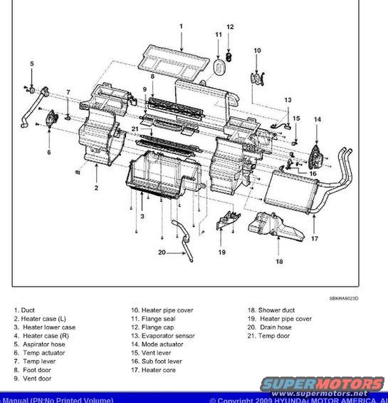
Exploded parts diagram of the heater unit with a numbered legend of ducts, cases, doors, evaporator sensor and heater core.
Part of 2010-2016 Hyundai Genesis Coupe Exploded Parts Diagrams
This document is an exploded parts diagram of the heater unit (HVAC heater assembly) from a Hyundai service manual, copyrighted 2009 by Hyundai Motor America and uploaded as applying to a 2010 Hyundai Genesis (Genesis Coupe, based on companion documents in the album). The illustration, referenced by drawing code SBKHA9023D, shows the complete heater unit disassembled into 21 numbered components, illustrating how each part fits together. The legend identifies each callout: the duct (1), left and right heater cases (2, 4), heater lower case (3), aspirator hose (5), temp actuator (6), temp lever (7), foot door (8), vent door (9), heater pipe covers (10, 19), flange seal (11), flange cap (12), evaporator sensor (13), mode actuator (14), vent lever (15), sub foot lever (16), heater core (17), shower duct (18), drain hose (20), and temp door (21). A reader can use this diagram to identify heater box components by name and location, understand the order and orientation of assembly/disassembly, and locate parts such as the heater core, blend/temp door actuators, and evaporator sensor when servicing or rebuilding the HVAC heater unit. The footer indicates it comes from an electronic (no printed volume) Hyundai service manual.
Is this accurate? Sign in to help verify it.
Frequently asked questions
- What parts make up the heater unit assembly in this diagram?
- The diagram shows 21 parts: duct, heater case (L), heater lower case, heater case (R), aspirator hose, temp actuator, temp lever, foot door, vent door, heater pipe cover, flange seal, flange cap, evaporator sensor, mode actuator, vent lever, sub foot lever, heater core, shower duct, a second heater pipe cover, drain hose, and temp door.
- Which callout number is the heater core?
- The heater core is item 17 in the exploded view, shown at the right side of the assembly with heater pipes attached.
- Where is the evaporator sensor in this heater unit diagram?
- The evaporator sensor is item 13, shown near the upper right of the heater case assembly.
- What actuators are part of the heater unit?
- Two actuators are shown: the temp actuator (item 6) on the left side of the case and the mode actuator (item 14) on the right side.
- What is the diagram reference code for this heater unit illustration?
- The illustration is labeled SBKHA9023D.
Comments
More from this build









No comments yet.