Home/
Registry/
Hyundai/
Genesis Coupe/
2010-2016/
“Coupe”/
Photo
supermotors.net/registry/media/1145843
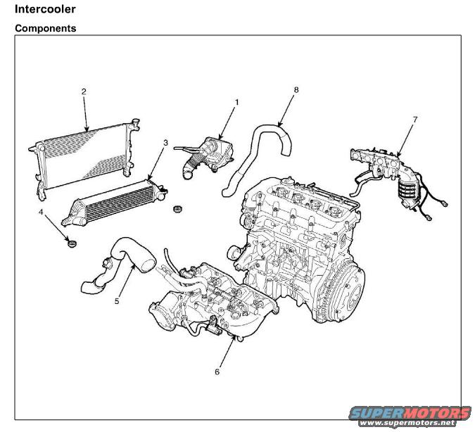
2010 Hyundai Genesis Intercooler Components Exploded Diagram - IC Pipes
Reference · 2010-2016 Genesis CoupeAll 14 exploded parts diagrams

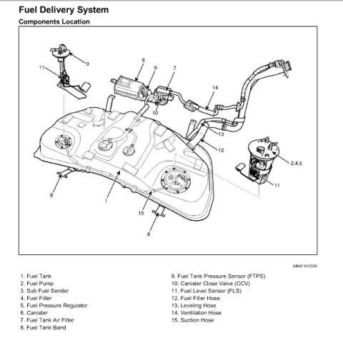
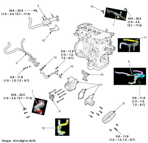
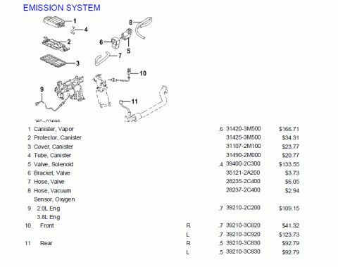
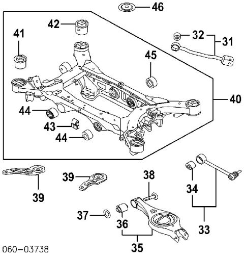








Exploded parts diagram of the intercooler system showing radiator, intercooler, hoses and engine block components.
Part of 2010-2016 Hyundai Genesis Coupe Exploded Parts Diagrams
This document is a single page from a service manual showing the 'Intercooler: Components' exploded view for a turbocharged inline four-cylinder engine. The illustration depicts the complete engine assembly along with the removed intercooler system components, each identified by a numbered callout (1 through 8). Callout 2 indicates a radiator/heat-exchanger style panel, callout 3 indicates the finned intercooler core, and callout 4 a small mounting grommet beneath it. Callouts 5 and 8 point to the intercooler hoses/pipes routing air to and from the intercooler, callout 1 to a turbocharger or pipe assembly above the engine, callout 6 to the intake manifold on the engine, and callout 7 to the exhaust manifold/turbocharger assembly with attached wiring on the right. No text legend naming the numbered parts, no torque specifications, and no part numbers appear on this page; the legend is presumably on an adjacent manual page. A reader can learn the general arrangement and relative positions of the intercooler system components for disassembly/reassembly reference, but not part names or fastener specs from this page alone.
Is this accurate? Sign in to help verify it.
Frequently asked questions
- What does this diagram show?
- It is the 'Intercooler: Components' exploded view showing an engine assembly with eight numbered callouts identifying intercooler system parts such as the intercooler core, hoses/pipes, manifolds, and related components.
- Does the diagram identify the parts by name?
- No. The components are only numbered 1 through 8; no legend or parts list naming each number is visible on this page.
- How many components are called out in the intercooler exploded view?
- Eight components are called out, numbered 1 through 8.
- Are torque specs or part numbers included?
- No torque values or part numbers appear anywhere on this page, it is illustration only.

No comments yet.