Home/
Registry/
Hyundai/
Genesis Coupe/
2010-2016/
“Coupe”/
Photo
supermotors.net/registry/media/1142116
2010 Hyundai Genesis Coupe Heater Unit Component Location Diagram
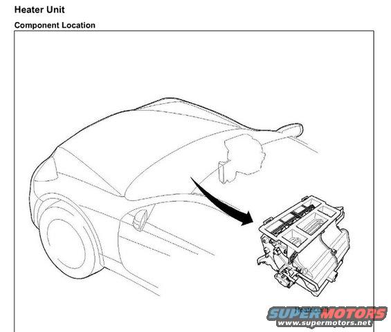
Component location illustration showing the heater unit position within the vehicle.
Part of 2010-2016 Hyundai Genesis Coupe Service Procedures
This is a single page from a service manual section titled "Heater Unit" showing the "Component Location" of the heater unit. The page consists of a line illustration of a two-door coupe body viewed from the front three-quarter angle, with a large arrow pointing from the dashboard/firewall area of the vehicle to a detailed exploded-view drawing of the heater unit assembly, labeled "Heater unit." The diagram indicates that the heater unit is located behind the dashboard in the center of the vehicle. There are no part numbers, torque specifications, tables, or written procedures on this page, it serves purely as a locator diagram to orient the technician before removal/installation or inspection procedures, which are presumably contained on subsequent pages (companion files "Heater unit 2-4.jpg" exist in the same album). The document itself contains no year, make, or model text, but the body style shown is consistent with the uploader's claimed 2010 Hyundai Genesis Coupe. Readers can learn from this page only where the heater unit is physically situated in the vehicle.
Is this accurate? Sign in to help verify it.
Frequently asked questions
- Where is the heater unit located on the Genesis Coupe?
- According to the component location diagram, the heater unit is located behind the dashboard, roughly centered in the vehicle at the firewall area.
- What does this service manual page show?
- It is the "Component Location" page of the "Heater Unit" section, showing an illustration of the car with an arrow pointing to the heater unit assembly behind the dash.
- Does this page include removal instructions or torque specs for the heater unit?
- No. This page only shows the component location illustration; it contains no procedures, part numbers, or torque values.
Comments
More from this build









No comments yet.