Home/
Registry/
Hyundai/
Genesis Coupe/
2010-2016/
“Coupe”/
Photo
supermotors.net/registry/media/1157884
2010 Hyundai Genesis Coupe Headlamp Wiring Diagram SD921-1 - Head Lamps (1)
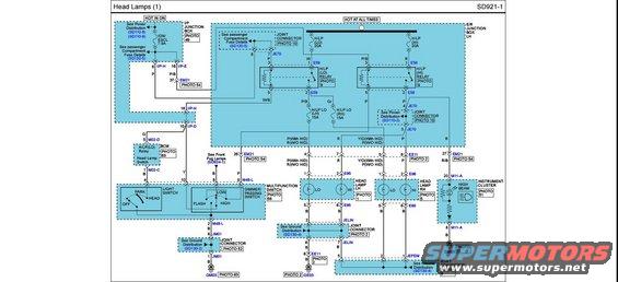
Head lamps wiring diagram showing junction boxes, multifunction switch connections and instrument cluster paths.
Part of 2010-2016 Hyundai Genesis Coupe Wiring Diagrams
This is page SD921-1, "Head Lamps (1)", a factory-style wiring diagram covering the headlamp circuit. Power flows from two sources: a "HOT IN ON" feed through the I/P Junction Box via a 7.5A IGN/ESCL fuse, and "HOT AT ALL TIMES" feeds through the E/R Junction Box LH via 20A H/LP (LO) and 20A H/LP (HI) fuses, plus 15A H/LP LO (LH) and 15A H/LP LO (RH) fuses. The diagram shows the H/LP (LO) relay (connector E59) and H/LP (HI) relay (connector E58), the BCM (M02-D/M02-C) with head lamp switch input, the multifunction switch (M48-L) containing the light switch (OFF/PARK/HEAD) and dimmer/passing switch (LOW/FLASH/HIGH), left and right headlamps (connectors E95 and E96 with LO and HI filaments), and the instrument cluster high-beam indicator (M11-A). Wire colors are labeled (P, P/B, W, W/B, R, Gr, Y, G, B, R/B), with variations noted for HID versus non-HID equipped vehicles (e.g., P with HID / R w/o HID). Grounds run through joint connectors JM01, JELIN, and JEFEM to ground points GM03, GM01, and GE03. Cross-references point to Power Distribution (SD110-2/8/9), fuse details (SD120-5), ground distribution (SD130-2/4), and front fog lamps (SD924-1).
Is this accurate? Sign in to help verify it.
Frequently asked questions
- What size are the headlamp fuses in this diagram?
- H/LP (LO) and H/LP (HI) are each 20A in the E/R Junction Box LH; H/LP LO (LH) and H/LP LO (RH) are each 15A. A 7.5A IGN/ESCL fuse in the I/P Junction Box feeds the HOT IN ON circuit.
- Which relays control the headlights?
- The H/LP (LO) relay (connector E59) and the H/LP (HI) relay (connector E58), both located in the E/R Junction Box LH.
- What connectors are used at the headlamps?
- The left headlamp uses connector E95 and the right headlamp uses connector E96, with pins 1 (LO) and 2 (HI) for power and pins 5 and 3 for ground (black wires).
- Do wire colors differ between HID and non-HID vehicles?
- Yes. For example, one circuit is P (With HID) / R (W/O HID) and another is Y/O (With HID) / P (W/O HID).
- Where is the high-beam indicator shown?
- In the instrument cluster (PHOTO 51), connected through pins 20 and 8 of connector M11-A, grounded at GM01.
Comments
More from this build









No comments yet.