Home/
Registry/
Hyundai/
Genesis Coupe/
2010-2016/
“Coupe”/
Photo
supermotors.net/registry/media/1158203
2010 Hyundai Genesis Coupe DRL Wiring Diagram SD958-1 - Daytime Running Lights
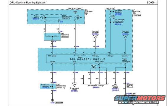
Wiring diagram of the daytime running lights system showing the DRL control module, resistor and relay connections.
Part of 2010-2016 Hyundai Genesis Coupe Wiring Diagrams
This is page SD958-1 of a Hyundai factory-style wiring diagram covering the DRL (Daytime Running Lights) circuit, sheet 1. It shows the DRL Control Module and its connections: power from the E/R (engine room) junction box LH via the DRL B/HORN 15A fuse (hot at all times) and from the I/P junction box via the IGN/ESCL 7.5A fuse (hot in ON). Module pins are labeled for DRL resistor (pin 10), battery (pins 14, 7), high relay (pin 15), ON input (pin 13), low relay (pin 5), ground (pin 6), IND., brake switch, and engine running input signal. Inputs come from the H/LP (HI) and (LO) relays (see SD958-2). Outputs route to the instrument cluster, indicators and gauges (SD940-1), the charging system (SD373-1/-2), and the generator via connectors CHG06 (G4KF engine) or CLG06 (G6DA engine). Wire colors shown include Br, L/B, R, Y/B, B, G, O/B, P/B, Br/O, and Gr. Connector IDs include JE70, E09, JM01, GM03, and EC21, with photo references (Photos 7, 10, 13/25, 19, 49, 52, 63) and cross-references to power distribution (SD110-6/-8), fuse details (SD120-5), and ground distribution (SD130-2).
Is this accurate? Sign in to help verify it.
Frequently asked questions
- What fuse powers the DRL circuit on the Genesis Coupe?
- The DRL B/HORN 15A fuse in the E/R (engine room) junction box LH, hot at all times, plus the IGN/ESCL 7.5A circuit in the I/P junction box, hot in ON.
- What are the main inputs to the DRL Control Module?
- DRL resistor (pin 10), battery (pins 14 and 7), high relay (pin 15) from the H/LP (HI) relay, ON input (pin 13), low relay (pin 5) from the H/LP (LO) relay, brake switch, and engine running input signal.
- Where does the engine running input signal come from?
- From the charging system/generator via connector EC21 pin 13 (Gr wire) and connector CHG06 (G4KF engine) or CLG06 (G6DA engine) at the generator.
- Where is the DRL module grounded?
- Module pin 17 (I/P-D, B wire) goes through joint connector JM01 (see Ground Distribution SD130-2) to ground point GM03 (Photo 63).
- What diagram pages are cross-referenced for the H/LP relays?
- Both the H/LP (HI) relay and H/LP (LO) relay reference sheet SD958-2, the continuation of the DRL diagram.
Comments
More from this build









No comments yet.