Home/
Registry/
Hyundai/
Genesis Coupe/
2010-2016/
“Coupe”/
Photo
supermotors.net/registry/media/1154849
2010 Hyundai Genesis Coupe Tail Lamp Connectors F57 & F58 Pinout Diagram

Reference · 2010-2016 Genesis CoupeAll 79 wiring diagrams
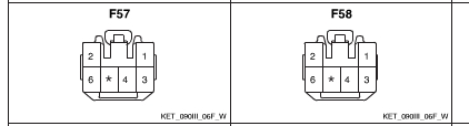
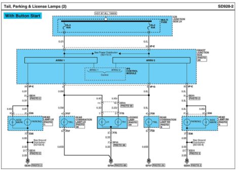
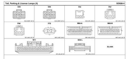








Connector terminal pinout diagrams for connectors F57 and F58 with numbered six-cavity layouts.
Part of 2010-2016 Hyundai Genesis Coupe Wiring Diagrams
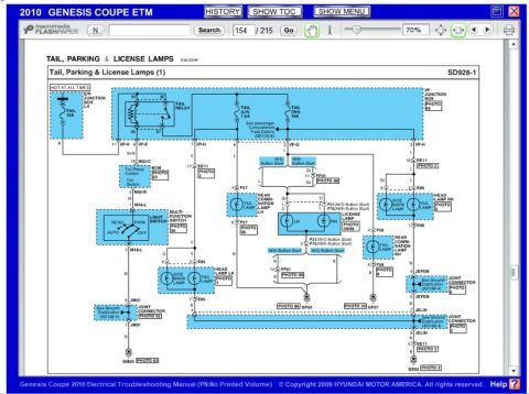
This document is a connector pinout diagram showing two electrical connectors labeled F57 and F58, identified by the uploader as tail lamp connectors for a 2010 Hyundai Genesis Coupe (BK1 chassis). Both connectors share an identical housing style and pin arrangement: a 6-cavity connector with pins 2 and 1 on the top row, and pins 6, an unpopulated/keyed position (marked with an asterisk), 4, and 3 on the bottom row. The connectors are drawn face-on, showing the housing outline with locking tabs. Each connector drawing carries the reference code KET_090III_06F_W, which appears to identify the connector housing type/drawing. No wire colors, circuit functions, year, model, or part numbers are printed on this excerpt itself; it serves purely as a physical pin-numbering reference to be used alongside the related tail light wiring diagram in the same album. A reader can learn the pin numbering orientation for connectors F57 and F58 so they can correlate pin numbers from a wiring diagram to the physical connector when testing or repairing tail lamp circuits.
Is this accurate? Sign in to help verify it.
Frequently asked questions
- What connectors are shown in this diagram?
- Two connectors labeled F57 and F58, each drawn with their pin cavity numbering.
- What is the pin arrangement of connectors F57 and F58?
- Both have the same layout: pins 2 and 1 on the top row, and pins 6, an asterisk-marked (unused/keyed) position, 4, and 3 on the bottom row.
- What does the asterisk (*) position in the connector mean?
- The document only shows an asterisk in one cavity between pins 6 and 4; it does not explain it, but it indicates a position without a numbered pin.
- Is there a connector reference code on the drawing?
- Yes, both connector drawings are marked KET_090III_06F_W.

No comments yet.