Home/
Registry/
Hyundai/
Genesis Coupe/
2010-2016/
“Coupe”/
Photo
supermotors.net/registry/media/1164328
Hyundai Genesis Coupe 3.8L G6DA MFI Control System Wiring Diagram SD313-14
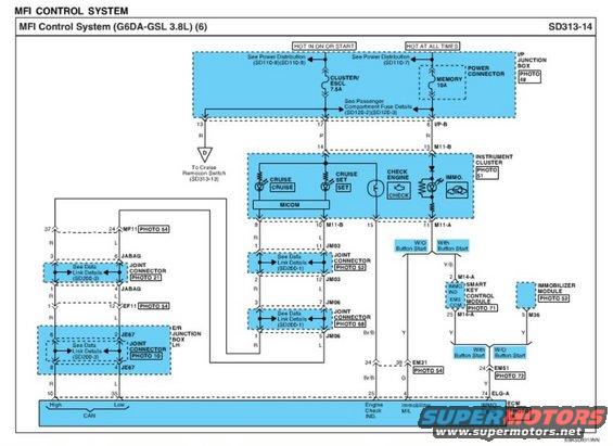
Wiring diagram showing cruise control, immobilizer, instrument cluster and CAN circuits for a 3.8L MFI system.
Part of 2010-2016 Hyundai Genesis Coupe Wiring Diagrams
This document is page 6 of the Multiport Fuel Injection (MFI) Control System wiring diagram, sheet SD313-14, for the Hyundai G6DA-GSL 3.8L engine (Genesis Coupe BK1). It shows power feeds from the I/P Junction Box: the CLUSTER/ESCL 7.5A fuse (hot in ON or START) and the MEMORY 10A fuse (hot at all times), with references to Power Distribution pages SD110-7/8/9 and passenger compartment fuse details SD120-2/SD120-3. The diagram traces circuits to the instrument cluster (PHOTO 51), including the CRUISE, CRUISE SET, CHECK ENGINE, and IMMO indicator lamps driven through the cluster MICOM, and a branch to the cruise remocon switch (SD313-13). CAN High and Low lines route through joint connectors JABAG, JM03, JM06, JE67, MF11, and EF11 (with data-link detail references SD200-1 and SD200-3) to ECM pins 10 (CAN High) and 35 (CAN Low). Other ECM connections shown are pin 25 Engine Check indicator (Br/B), pin 4 Immobilizer MIL (G), and pin 74 ELG-A IMMO signal (Y). Immobilizer signals split between the Smart Key Control Module M14-A (with button start) and Immobilizer Module M36 (without button start). Connector photo references and wire colors (R, L, P, Y, Y/B, Br/B, G) are labeled throughout.
Is this accurate? Sign in to help verify it.
Frequently asked questions
- Which fuses power the MFI control/instrument cluster circuits on this diagram?
- The CLUSTER/ESCL 7.5A fuse (hot in ON or START) and the MEMORY 10A fuse (hot at all times), both in the I/P Junction Box (PHOTO 49).
- Which ECM pins carry the CAN bus lines?
- ECM pin 10 is CAN High and pin 35 is CAN Low, routed through joint connectors including JABAG, JM03, JM06, JE67, MF11, and EF11.
- What indicator lamps in the instrument cluster are shown on this page?
- CRUISE, CRUISE SET, CHECK ENGINE, and IMMO indicators, all controlled through the cluster's MICOM.
- How does the immobilizer signal differ with and without button start?
- With Button Start, the signal goes to the Smart Key Control Module (connector M14-A, pins 2 and 25); without Button Start, it goes to the Immobilizer Module (connector M36, pin 5). Both route to ECM pin 74 (ELG-A, IMMO Signal, Y wire).
- Which ECM pin drives the Check Engine indicator?
- ECM pin 25 (Engine Check IND.) on a Br/B wire, which connects through connector EM21 (pins 34/38) to the cluster.
Comments
More from this build









No comments yet.