Home/
Registry/
Hyundai/
Genesis Coupe/
2010-2016/
“Coupe”/
Photo
supermotors.net/registry/media/1164326
Hyundai Genesis Coupe 3.8L G6DA MFI Wiring Diagram SD313-12 - O2 Sensors, MAF
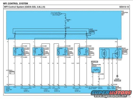
Wiring diagram showing oxygen sensor, oil temperature and mass air flow sensor circuits for a 3.8L MFI control system.
Part of 2010-2016 Hyundai Genesis Coupe Wiring Diagrams
This is page 4 of the Multiport Fuel Injection (MFI) Control System wiring diagram (sheet SD313-12) for the Hyundai G6DA-GSL 3.8L engine, consistent with the BK1 Genesis Coupe 3.8. The diagram shows power distribution from the Engine Control Relay (referenced from sheet SD313-9) through the SNSR-1 10A fuse in the right-hand E/R Junction Box, via joint connector JCL83 (pins 5, 6, 7, 8), to the heater circuits of four heated oxygen sensors: #1 (B1/S1, connector CLG93), #3 (B1/S2, CLG95), #4 (B2/S2, CLG96), and #2 (B2/S1, CLG94). Each sensor's heater (HTR.) and sensing element (SNSR) wiring is drawn with pin numbers and wire colors (P, L, Gr, Br, P/B, Br/B, Gr/B). It also covers the Mass Air Flow Sensor (CLG27) with its integrated ATS (air temperature sensor) and AFM elements, and the Oil Temperature Sensor (CLG03). All signal and heater lines terminate at ECM pins (e.g., 99 Engine Control Relay ON input, 38/39 O2 #1 HI/LO, 10 Oil Temp Signal, 14 ATS Signal, 30 AFM Signal, 18 Sensor Ground) on connectors ELG-A and CLG-B. Photo references (19, 27, 29, 33, 35, 36, 38, 41) point to connector location illustrations.
Is this accurate? Sign in to help verify it.
Frequently asked questions
- What fuse powers the oxygen sensor heaters on the 3.8L Genesis Coupe?
- The SNSR-1 10A fuse in the E/R Junction Box RH, fed from the Engine Control Relay (see SD313-9), supplies the heater circuits of all four oxygen sensors via joint connector JCL83.
- What are the connector numbers for the four oxygen sensors on the G6DA 3.8L?
- Oxygen Sensor #1 (B1/S1) uses CLG93, #3 (B1/S2) uses CLG95, #4 (B2/S2) uses CLG96, and #2 (B2/S1) uses CLG94.
- Which ECM pins receive the mass air flow sensor signals?
- The MAF sensor (connector CLG27) sends the ATS signal to ECM pin 14 and the AFM signal to ECM pin 30 (CLG-B), with sensor ground at pin 18.
- Where does the oil temperature sensor connect on this diagram?
- The Oil Temperature Sensor uses connector CLG03; its signal goes to ECM pin 10 (Oil Temperature Sensor Signal) and its ground to the Sensor Ground line at ECM pin 18.
- Which ECM pins are the HI/LO signals for Oxygen Sensor #1?
- Oxygen Sensor #1's HI signal goes to ECM pin 38 and LO to pin 39, with its heater on pin 91.
Comments
More from this build









No comments yet.