Home/
Registry/
Hyundai/
Genesis Coupe/
2010-2016/
“Coupe”/
Photo
supermotors.net/registry/media/1164327
Hyundai Genesis Coupe 3.8L G6DA MFI Wiring Diagram SD313-13 - Sensors & Cruise
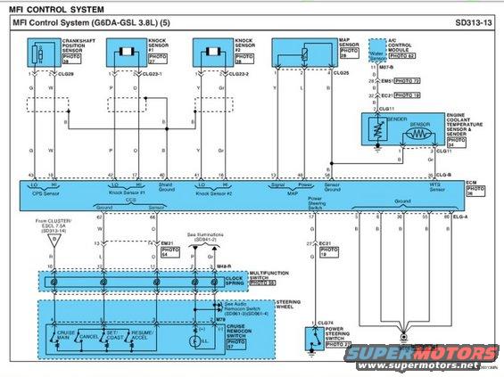
Wiring diagram showing crankshaft position, knock, MAP sensor and steering wheel switch circuits.
Part of 2010-2016 Hyundai Genesis Coupe Wiring Diagrams
This is page 5 of the Multiport Fuel Injection (MFI) Control System wiring diagram, sheet SD313-13, for the G6DA-GSL 3.8L engine. It shows the ECM (PHOTO 36) connections to several engine sensors and driver controls. Sensor circuits detailed include the crankshaft position sensor (connector CLG29, ECM pins 43 LO / 18 HI), knock sensor #1 (CLG23-1, pins 42/17), knock sensor #2 (CLG23-2, pins 41/16) with shield ground at pin 40, the MAP sensor (CLG25, signal pin 13, power pin 48, sensor ground pin 56), and the engine coolant temperature sensor & sender (CLG11, WTS sensor at ECM pin 35), which also feeds the A/C control module. Wire colors (G, W, P, O, B, Gr, Y, L, R) are labeled throughout. The lower half shows the cruise control system (CCS) circuits: ECM pins 62 (ground) and 66 (sensor) route through connector EM21 and clock spring/multifunction switch (M48-R) to the steering-wheel-mounted cruise remocon switch (M79) with MAIN, CANCEL, SET/COAST, and RESUME/ACCEL buttons plus illumination. The power steering switch (CLG74) connects to ECM pin 17 via EC21. ECM grounds (pins 5, 6, 30, 55, 80) terminate at ground point GE08. Cross-references to other diagram sheets (SD313-14, SD941-2, SD961-3/4) and component photos are included.
Is this accurate? Sign in to help verify it.
Frequently asked questions
- Which ECM pins connect to the crankshaft position sensor on the 3.8L G6DA engine?
- The crankshaft position sensor (connector CLG29) connects to ECM pin 43 (LO, wire G) and pin 18 (HI, wire W).
- What are the knock sensor connections shown on diagram SD313-13?
- Knock sensor #1 (connector CLG23-1) goes to ECM pins 42 (LO) and 17 (HI) with P and O wires; knock sensor #2 (CLG23-2) goes to pins 41 (LO) and 16 (HI); the shield ground is at ECM pin 40.
- How is the MAP sensor wired to the ECM?
- The MAP sensor uses connector CLG25 with wires Y, L, and B; its signal goes to ECM pin 13, power to pin 48, and sensor ground to pin 56.
- What buttons are on the cruise remocon switch and how does it connect?
- The cruise remocon switch (PHOTO 57) on the steering wheel has CRUISE MAIN, CANCEL, SET/COAST, and RESUME/ACCEL buttons plus illumination. It connects via connector M79 through the clock spring/multifunction switch (M48-R) to ECM pins 62 (CCS ground) and 66 (CCS sensor) via connector EM21.
- Where does the power steering switch connect on this diagram?
- The power steering switch (connector CLG74, PHOTO 27) connects through connector EC21 pin 27 (wire G) to ECM pin 17, and to ground on the other side.
Comments
More from this build









No comments yet.