Ford Steering Column Wiring Diagram - Multi-Function Switch & Shift Interlock
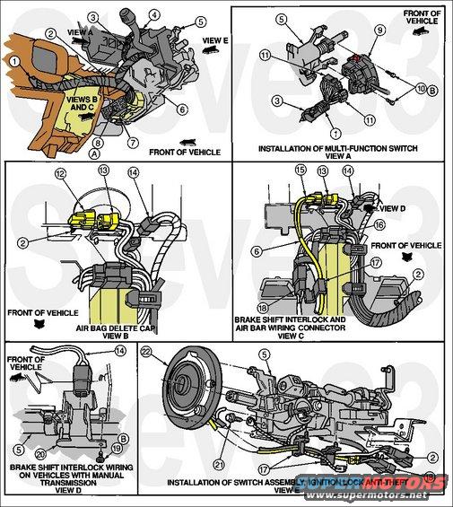
'95 Steering Column Wiring
IF THE IMAGE IS TOO SMALL, click it.
1 14401 Wiring Assembly
2 -- Wiring Locator, Locate in Hole Provided (Part of 14401)
3 -- To E4OD Pigtail
4 -- E4OD Pigtail (Part of 14401)
5 3514 Steering Column Assembly
6 9C899 Pigtail
14A664 Pigtail (with Air Bag)
7 15572 Ignition Switch
8 -- Bolt (Part of 9C899)
9 13K359 Turn Signal and Windshield Wiper Switch
10 390345-S36 Fastener
11 -- To Multi-Function Switch
12 14A282 Air Bag Delete Cap
13 -- Air Bag Wiring (See View D for Air Bag Delete) (Part of 14A664)
14 -- To Brake Shift Interlock
15 -- To Air Bag
16 -- To 9C899 Brush Assembly (Without Air Bag) to 14A664 Clockspring (with Air Bag)
17 -- Wiring Retainers, Locate in Holes Provided (Part of 14401)
18 19A438 Switch Assembly, Anti-Theft Ignition Lock
19 N806584-S58 Screw
20 14A163 Wiring Retainer (Brake Shift Interlock Delete with Manual Transmission)
21 390345-S36 Screw, Anti-Theft Ground
22 14A664 Air Bag Sliding Contact
A -- Tighten to 1 N-m (9 Lb-In)
B -- Tighten to 8-10 N-m (71-89 Lb-In)
See also: .
.  .
. 
Is this accurate? Sign in to help verify it.
Frequently asked questions
- What views are included in this steering column wiring diagram?
- It includes a main column overview plus View A (Installation of Multi-Function Switch), View B (Air Bag Delete Cap), View C (Brake Shift Interlock and Air Bag Wiring Connector), View D (Brake Shift Interlock Wiring on Vehicles with Manual Transmission), and View E (Installation of Switch Assembly, Ignition Lock Anti-Theft).
- Does this diagram show the brake shift interlock wiring for manual transmissions?
- Yes. View D specifically shows 'Brake Shift Interlock Wiring on Vehicles with Manual Transmission' with callouts 5, 14, 19, and 20.
- Where is the multi-function switch installation shown?
- View A, labeled 'Installation of Multi-Function Switch,' shows the switch, its mounting hardware, and wiring connectors with callouts 1, 3, 5, 9, 10, and 11.
- Does the diagram identify part names or part numbers for the numbered callouts?
- No. The page shows only numbered callouts (1-22) with no legend, part names, part numbers, or torque values visible; the key is likely on an accompanying page.
- Is airbag-related wiring shown on this diagram?
- Yes. View B is labeled 'Air Bag Delete Cap' and View C is labeled 'Brake Shift Interlock and Air Bar Wiring Connector' (air bag), showing connectors and harness routing at the column.
Comments
More from this build








No comments yet.