Home/
Registry/
Hyundai/
Genesis Coupe/
2010-2016/
“Coupe”/
Photo
supermotors.net/registry/media/1164429
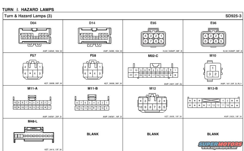
Hyundai Genesis Coupe BK1 Turn & Hazard Lamp Connector Pinouts SD925-3
Reference · 2010-2016 Genesis CoupeAll 23 schematics

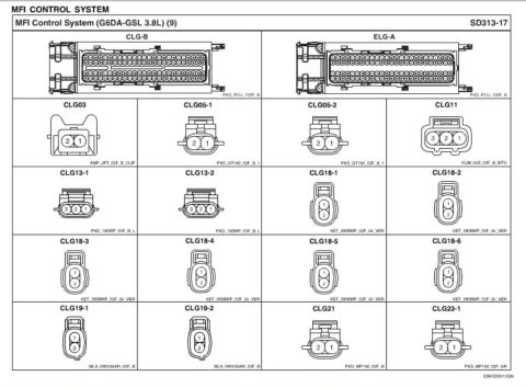
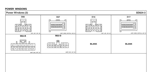
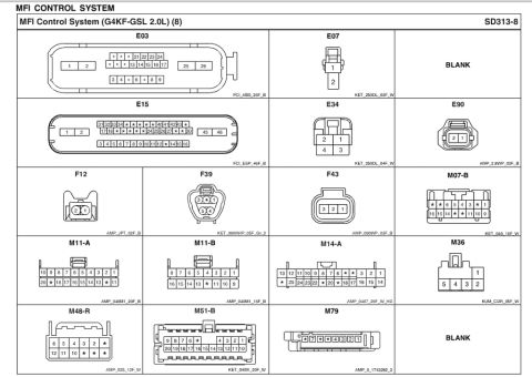
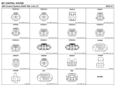








Connector identification page for the turn and hazard lamp system showing connector terminal layouts.
Part of 2010-2016 Hyundai Genesis Coupe Schematics
This document is page SD925-3 from a Hyundai electrical troubleshooting/wiring manual, titled "Turn & Hazard Lamps (3)." It is a connector reference sheet showing the physical face views (pinout cavity diagrams) of the electrical connectors used in the turn signal and hazard lamp circuits. Thirteen connectors are illustrated: D04, D14, E95, E96, F57, F58, M02-C, M10, M11-A, M11-B, M12, M13-B, and M48-L, with three grid cells marked BLANK. Each connector drawing shows the numbered pin cavities (asterisks marking unused positions) and is captioned with its housing/part identification code, such as AMP_040MI_16M_W (D04), KUM_NMWP_08F_B (E95/E96), KET_090III_06F_W (F57/F58), AMP_0407_22F_Gr (M02-C), AMP_187_03F_B_RLY (M10 relay socket), AMP_040M1_20F_B (M11-A), AMP_040M1_16F_B (M11-B), KET_090III_10F_W (M12), AMP_0925_18F_W (M13-B), and KET_0419_13F_W (M48-L). A reader can use this page to identify connector shapes, pin numbering orientation, cavity counts, and housing part codes when tracing or repairing turn/hazard lamp wiring. No wire colors, fuse values, or circuit paths are shown on this page; it serves as a companion to the associated wiring diagram pages.
Is this accurate? Sign in to help verify it.
Frequently asked questions
- What connectors are used in the Genesis Coupe turn and hazard lamp circuit?
- Page SD925-3 shows connectors D04, D14, E95, E96, F57, F58, M02-C, M10, M11-A, M11-B, M12, M13-B, and M48-L for the turn & hazard lamps circuit.
- What is the connector housing code for the E95 and E96 connectors?
- Both E95 and E96 are 8-pin connectors with housing code KUM_NMWP_08F_B, arranged as pins 4-3-2-1 on the top row and 8-7-6-5 on the bottom row.
- How many pins does the M02-C connector have and what is its part code?
- M02-C is a 22-cavity connector (positions 1-22, several marked with * as unused) with part code AMP_0407_22F_Gr.
- What is connector M10 on this diagram?
- M10 is a 3-position connector labeled AMP_187_03F_B_RLY, with pin 1 on top and pins 3 and 2 on the bottom row.
- Do the asterisks in the connector drawings mean anything?
- The asterisk positions in the pin diagrams indicate cavities that are not numbered/populated in these turn & hazard lamp connectors.

No comments yet.