Home/
Registry/
Ford/
Bronco/
1980-1986/
“That dirty old truck”/
Photo
supermotors.net/registry/media/1174875
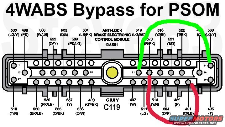
Ford 4WABS Bypass for PSOM - ABS Module Connector C119 Wiring Diagram
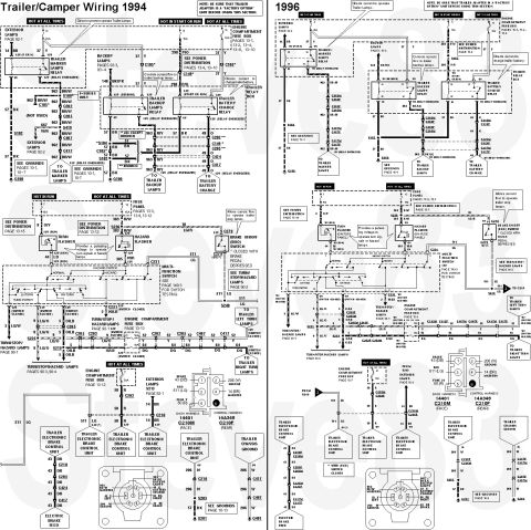
Reference · 1980-1986 BroncoAll 92 wiring diagrams

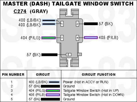
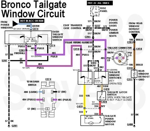
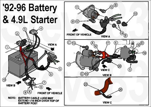







4WABS Bypass for PSOM
IF THE IMAGE IS TOO SMALL, click it.
When the 4WABS module fails (and they all will eventually), it's virtually impossible to find a replacement or reman (in 2026). So until they become available, this workaround will allow the speedometer, cruise, & transmission to continue working by delivering the ABS sensor signal directly to the PSOM, like in '92 Broncos and '92-96/7 Fs.
See also:
 .
.  .
.  .
. 
Part of 1980-1986 Ford Bronco Wiring Diagrams
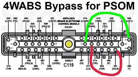
This document is a hand-annotated wiring diagram titled "4WABS Bypass for PSOM," showing the connector face of the Ford Anti-Lock Brake Electronic Control Module (part designation 12A581), gray connector C119. Every cavity of the module connector is labeled with its circuit number and wire color code, including circuits 530 (LG/Y), 498 (PK), 606 (W/LB), 532 (O/Y), 603 (DG), 599 (PK/LG), 601 (LB/PK), 519 (LG/BK), 523 (R/PK), 516 (Y/BK), 521 (T/O), 522 (T/BK) on the top row and 510 (T/R), 538 (PK/LB), 960 (BK/LB), 887 (Y), 886 (O/BK), 836 (O/W), 499 (GY/BK), 497 (W), 511 (LG), 514 (Y/R), 604 (O/R), 462 (P), 491 (O/LB), 495 (T) on the bottom row. Pin position numbers 1, 15, 27, 20, 21, 14, 26, and 40 are shown. Colored overlay lines illustrate the bypass: a green jumper linking circuit 519 (LG/BK) at pin 21 to circuit 530 (LG/Y) near pin 14, and a red jumper linking circuit 523 (R/PK) to circuit 491 (O/LB). This allows the Programmable Speedometer/Odometer Module (PSOM) signal path to be maintained when the 4WABS module is bypassed or removed.
Is this accurate? Sign in to help verify it.
Frequently asked questions
- Which connector does the 4WABS bypass for PSOM use?
- The gray connector C119 at the Anti-Lock Brake Electronic Control Module (12A581).
- Which wires are jumpered to bypass the 4WABS module for the PSOM?
- The diagram shows a green jumper from circuit 519 (LG/BK, pin 21) to circuit 530 (LG/Y, near pin 14), and a red jumper from circuit 523 (R/PK) to circuit 491 (O/LB).
- What wire color is circuit 519 at the ABS module?
- Circuit 519 is Light Green/Black (LG/BK).
- What is the Ford part designation for the anti-lock brake control module shown?
- The module is labeled 12A581 (Anti-Lock Brake Electronic Control Module).
- How many pin positions are shown on the ABS module connector?
- Pin numbers up to 40 are shown, with positions 1, 15, 27, 20, 21, 14, 26 and 40 labeled on the connector face.






No comments yet.