Hayden Electric Fan Thermostat Wiring Diagram P 12623-IS w/ Relay Mod
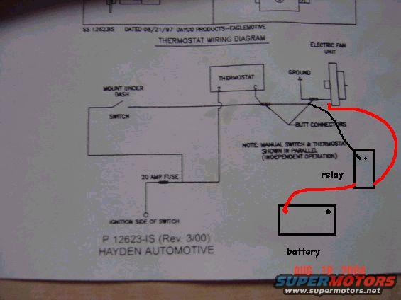
Wiring diagram for an electric cooling fan showing thermostat, switch, 20 amp fuse, relay and battery connections.
Part of 1978-1979 Ford Bronco Wiring Diagrams
This document is a scanned instruction sheet from Hayden Automotive (P 12623-IS, Rev. 3/00; earlier reference SS 1.2623IS dated 08/21/97, Dayco Products, Eaglemotive) showing a thermostat wiring diagram for an electric cooling fan installation. The diagram shows an electric fan unit connected to ground and to a thermostat, with a manual switch (to be mounted under the dash) wired in parallel with the thermostat for independent operation. Butt connectors are indicated at the junction points. Power for the circuit is taken from the ignition side of the switch through a 20-amp fuse. The uploader has added hand-drawn modifications in red marker: a relay inserted into the circuit between the fan/thermostat wiring and a battery, indicating a plan to relay-trigger the fan directly from the battery rather than powering it entirely through the switched circuit. The scan was uploaded to a 1979 Ford Bronco gallery as part of a set of wiring documents; the sheet itself is a generic universal fan-thermostat instruction, not vehicle-specific. Readers can learn the recommended Hayden wiring layout for an electric fan thermostat with manual override switch, the required fuse rating (20 amps), and the uploader's suggested relay/battery modification.
Is this accurate? Sign in to help verify it.
Frequently asked questions
- What fuse rating does the Hayden thermostat wiring diagram call for?
- A 20 amp fuse, wired between the ignition side of the switch and the rest of the circuit.
- How are the manual switch and thermostat wired in this diagram?
- The manual switch and thermostat are shown wired in parallel for independent operation, per the note on the diagram.
- Where should the manual switch be mounted?
- The diagram indicates the switch should be mounted under the dash.
- What part number is this Hayden instruction sheet?
- P 12623-IS (Rev. 3/00), from Hayden Automotive; it also references SS 1.2623IS dated 08/21/97, Dayco Products, Eaglemotive.
- What do the red hand-drawn additions show?
- They show a relay and a battery added to the circuit, indicating a modification to power the electric fan through a relay fed from the battery.
Comments
More from this build






No comments yet.