Hayden Electric Fan Thermostat Wiring Diagram P 12623-IS with Relay Mod
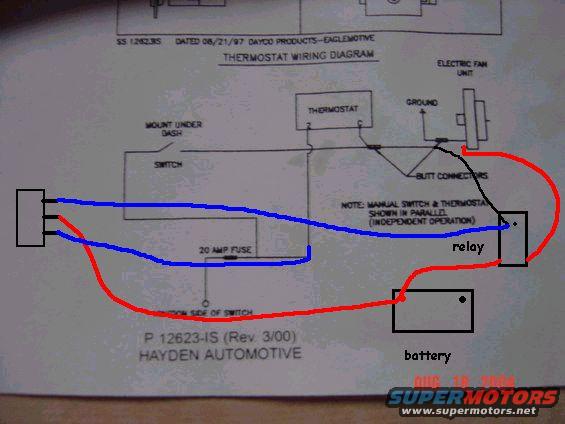
Wiring diagram for an electric cooling fan with annotated red and blue wire routing to relay, battery and switch.
Part of 1978-1979 Ford Bronco Wiring Diagrams
This is a scanned Hayden Automotive instruction sheet (P 12623-IS, Rev. 3/00; earlier revision SS 12623IS dated 08/21/97, Dayco Products, Eaglemotive) showing a thermostat wiring diagram for an aftermarket electric cooling fan installation. The printed diagram shows an electric fan unit connected to ground and to a thermostat, with a manual switch (marked "mount under dash") wired in parallel with the thermostat for independent operation, joined with butt connectors. Power runs through a 20 amp fuse to the ignition side of the switch. Over the printed diagram, the uploader has drawn colored lines in red and blue marker showing a modified hookup: red wiring runs from the battery (hand-labeled box) through a relay (hand-labeled box) to a connector block and up to the fan circuit, while blue wiring connects the switch/fused circuit to the relay trigger side. The scan documents both the manufacturer's stock wiring scheme (thermostat plus manual override switch in parallel) and the owner's relay-based modification to carry fan current from the battery instead of directly through the switch. A camera date stamp reads AUG 18 2004.
Is this accurate? Sign in to help verify it.
Frequently asked questions
- What fuse size does the Hayden thermostat wiring diagram call for?
- The diagram shows a 20 amp fuse in the circuit feeding the switch (ignition side of switch).
- How are the manual switch and thermostat connected in this Hayden fan wiring diagram?
- Per the printed note, the manual switch and thermostat are shown wired in parallel for independent operation, joined with butt connectors.
- Where should the manual fan switch be mounted according to the diagram?
- The diagram labels the switch location as 'mount under dash.'
- What part number and revision is this Hayden instruction sheet?
- It is P 12623-IS (Rev. 3/00); the header also shows SS 12623IS dated 08/21/97 from Dayco Products, Eaglemotive.
- What do the hand-drawn red and blue lines show?
- They show the uploader's modification adding a relay: red lines route power from the battery through the relay to the fan circuit, and blue lines connect the switched/fused circuit to the relay.
Comments
More from this build






No comments yet.