Electric Cooling Fan Relay & Thermostat Wiring Diagram - Ford Bronco
Reference · 1978-1979 BroncoAll 44 schematics
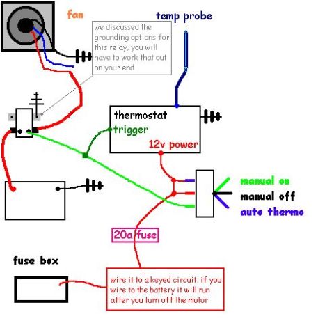
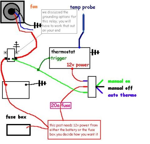
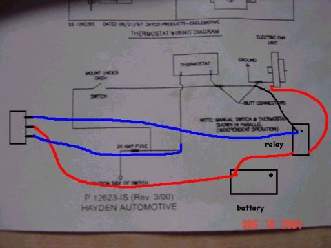


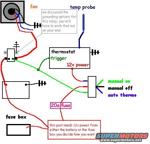
Hand-drawn electric fan wiring schematic showing fan relay, temp probe, thermostat trigger, 20A fuse, and 3-position manual-on/manual-off/auto-thermo switch.
Part of 1978-1979 Ford Bronco Schematics
This document is a hand-drawn wiring schematic (uploaded as "wirethis.jpg") showing how to wire an electric cooling fan with a relay and an adjustable thermostat controller. The diagram depicts a fan (upper left) wired through a relay, with a note stating "we discussed the grounding options for this relay, you will have to work that out on your end." A temperature probe (blue wire) connects to a thermostat module, which has a green "trigger" wire and a red "12v power" input. A three-position switch on the right offers "manual on" (green), "manual off" (black), and "auto thermo" (blue) modes, allowing the fan to be run manually or automatically via the thermostat. A 20-amp fuse is shown inline on the red power wire feeding the switch, with a callout explaining that "this post needs 12v power from either the battery or the fuse box. you decide how you want it." The battery and the vehicle's fuse box are drawn at the lower left as possible power sources. Wire colors used in the drawing include red (power), green (trigger/manual on), blue (temp probe/auto thermo), and black (grounds/manual off). The diagram gives an installer the basic circuit layout for an aftermarket electric fan conversion with manual and thermostatic control.
Is this accurate? Sign in to help verify it.
Frequently asked questions
- What size fuse does this electric fan wiring diagram call for?
- The diagram shows a 20a fuse inline on the 12v power wire feeding the control switch.
- What switch positions does the fan control switch have?
- Three positions: manual on (green wire), manual off (black wire), and auto thermo (blue wire).
- Where does the 12v power for the switch post come from?
- The diagram notes that the post needs 12v power from either the battery or the fuse box, the installer decides which source to use.
- How is the fan triggered automatically?
- A temp probe connects to a thermostat module, which sends a green trigger wire to the relay; when in 'auto thermo' mode the fan runs based on the thermostat.
- How is the relay grounded in this diagram?
- Grounding is not specified; a note says the grounding options for the relay were discussed and must be worked out by the installer.






No comments yet.