Ford Traction-Lok Limited-Slip Differential Exploded Parts Diagram

Reference · 1980-1986 BroncoAll 61 exploded parts diagrams
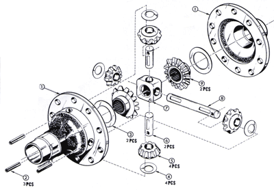
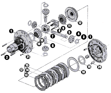
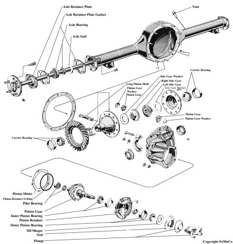
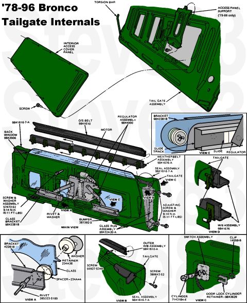
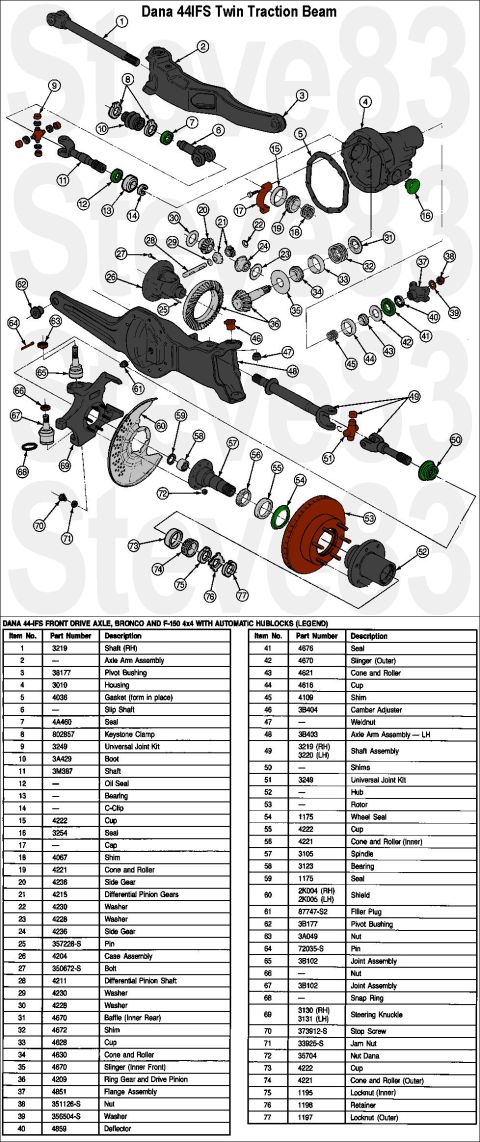
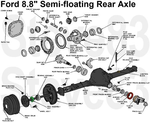
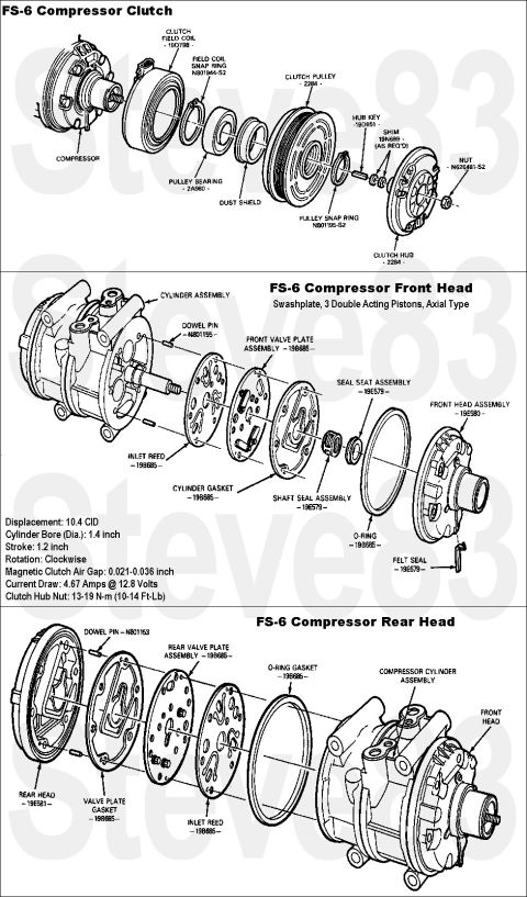
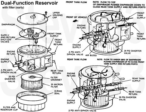
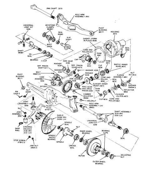
Exploded parts diagram of a limited-slip differential showing numbered case halves, side and pinion gears and clutch plate packs.
Part of 1980-1986 Ford Bronco Exploded Parts Diagrams
This document is an exploded parts diagram (illustration only) of a limited-slip "Traction-Lok" style differential carrier assembly, uploaded to a 1984 Ford Bronco gallery under the filename "traclockblowup.gif." The drawing shows the differential disassembled along its axis: the two ribbed case halves (callout 1) at either end, attaching bolts (2, 21), side gears and clutch hubs (10, 19, 6), pinion (spider) gears (4, 11) with thrust washers (3, 5) on a cross shaft (7) with retaining hardware (8, 9), the ring-gear-side flange (12), and a stack of alternating friction discs and steel clutch plates (13, 14, 15, 17) with shims/spacers (18, 19, 20). The callouts are numbered 1 through 21 (with 16 not clearly visible, and 1 and 19 repeated for duplicate parts), but no legend, parts list, part numbers, torque specifications, or text of any kind accompanies the image. A reader can learn the assembly order and relative arrangement of the clutch pack and gear components inside a limited-slip differential, but must consult a companion legend or service manual to identify each numbered part by name or part number.
Is this accurate? Sign in to help verify it.
Frequently asked questions
- What does this diagram show?
- It is an exploded view of a limited-slip (Traction-Lok type) differential, showing the two case halves, side gears, pinion gears on a cross shaft, and a multi-plate clutch pack with shims, identified by numbered callouts 1 through 21.
- Does the diagram include a parts list or part numbers?
- No. Only numbered callout balloons are visible; there is no legend, part names, part numbers, or text of any kind in the image.
- How many numbered components are called out?
- Callouts run from 1 to 21, with numbers 1 and 19 each appearing twice for duplicated parts; callout 16 is not clearly visible.
- Does the diagram show the clutch pack arrangement?
- Yes. The lower portion of the exploded view shows a stack of alternating friction and steel clutch plates (callouts 13, 14, 15, 17) along with adjacent shims/washers (18, 19, 20).
No comments yet.