Ford Open Carrier Differential Exploded Parts Diagram - 1984 Bronco

Reference · 1980-1986 BroncoAll 61 exploded parts diagrams
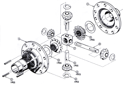
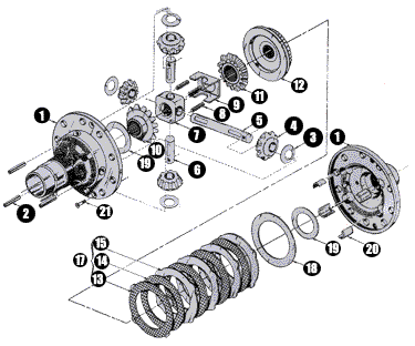
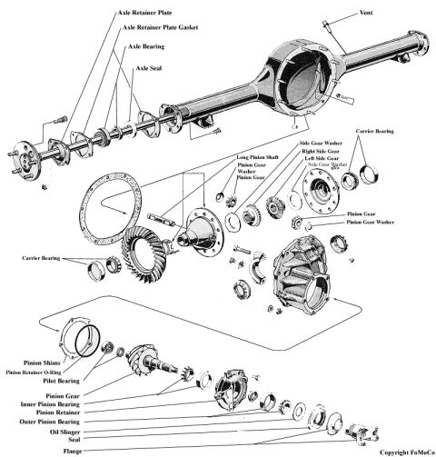
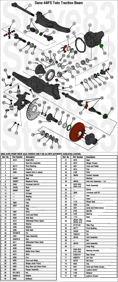
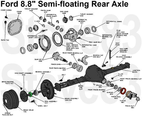
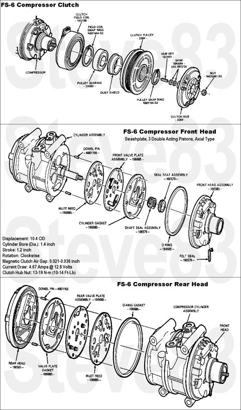
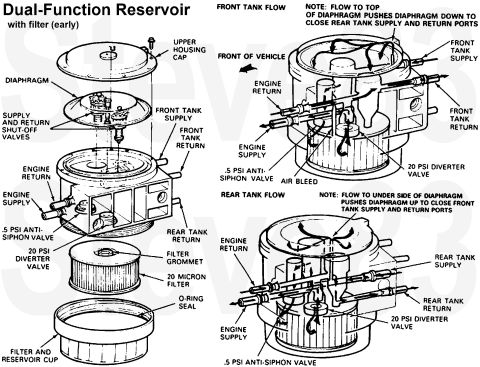
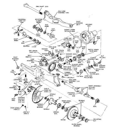
Exploded parts illustration of a differential carrier and gear assembly showing numbered side and pinion gears, thrust washers and piece counts.
Part of 1980-1986 Ford Bronco Exploded Parts Diagrams
This document is an exploded-view parts diagram of an open carrier differential assembly, uploaded to a 1984 Ford Bronco gallery under the filename "opencarrier.gif." The illustration shows the differential case split apart along its axis, with all internal components arranged in assembly order: the carrier housing, side gears, spider (pinion) gears, thrust washers, cross/pinion shaft, and the ring gear mounting flange with its bolt-hole pattern. Numbered circled callouts (1 through 9) identify each component, and quantity notations indicate how many of certain pieces are used, for example, "2 PCS" for the side gears and spider gears, "4 PCS" for the thrust washers, and "3 PCS" for what appear to be bolts or pins at the lower left. The diagram contains no legend, part numbers, torque specifications, or text labels beyond the callout numbers and piece counts, so the reader must rely on the visual arrangement to understand how the open differential is assembled and which parts come in multiples. It serves as a visual reference for anyone disassembling or rebuilding an open (non-limited-slip) differential carrier, showing the relative positions and orientation of all internal gears and hardware.
Is this accurate? Sign in to help verify it.
Frequently asked questions
- What does this diagram show?
- An exploded view of an open carrier differential assembly, with numbered callouts (1-9) identifying the carrier case, side gears, spider gears, thrust washers, cross shaft, and ring gear flange.
- How many spider/side gears are shown in the assembly?
- The diagram marks two components as '2 PCS' each (the side gears and the pinion/spider gears), for a total of four gears inside the carrier.
- How many thrust washers are used?
- Two groups of washers are labeled '4 PCS' each in the diagram, plus a '2 PCS' washer set near callout 9.
- Does the diagram include part numbers or torque specs?
- No. It contains only circled callout numbers 1-9 and piece-count labels (2 PCS, 3 PCS, 4 PCS); there is no legend, part number list, or torque data.
No comments yet.