SuperMotors SuperMotors SUPERMOTORS Search: try “orange Bronco on 35s”
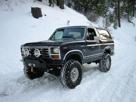
Home/ Registry/ Ford/ Bronco/ 1980-1986/ “That dirty old truck”/ Photo supermotors.net/registry/media/1172381

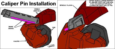
Ford Bronco Sliding Caliper Pin Installation Diagram - Brake Grease & Pin Tabs

Caliper Pin Installation diagram with labeled brake caliper, spindle and pad
Caliper Pin Installation diagram with labeled brake caliper, spindle and padOriginal file
Caliper Pin Installation diagram with labeled brake caliper, spindle and pad

Reference · 1980-1986 BroncoAll 40 service procedures
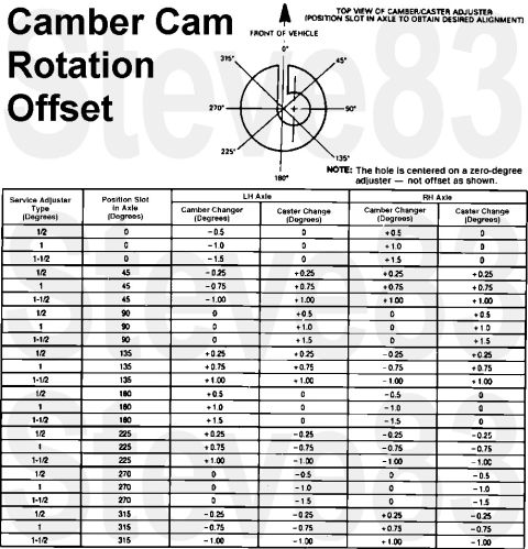
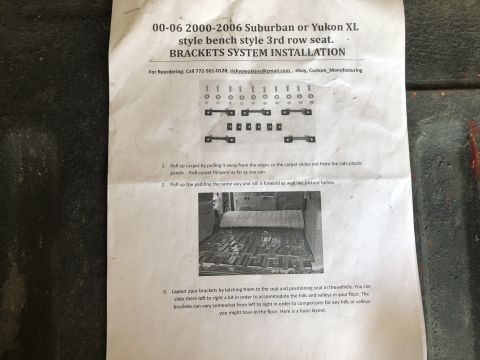
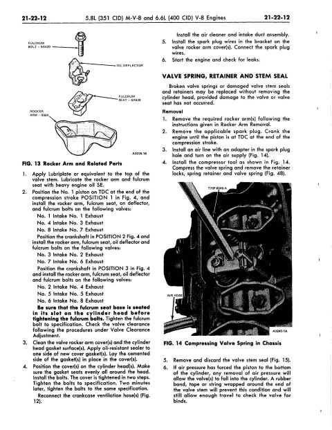
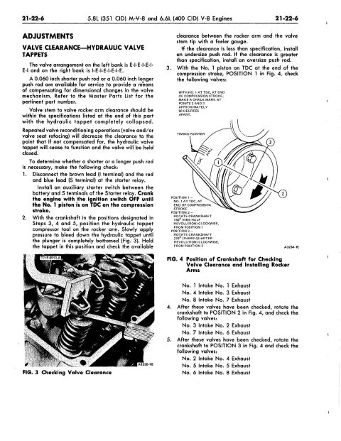
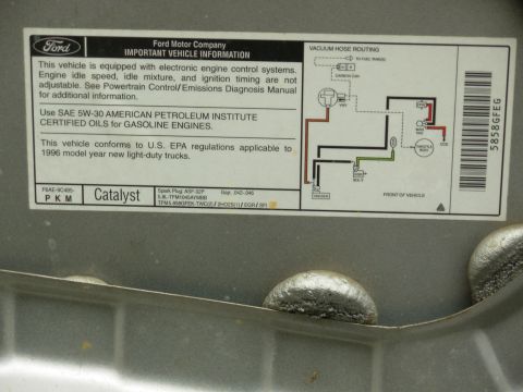
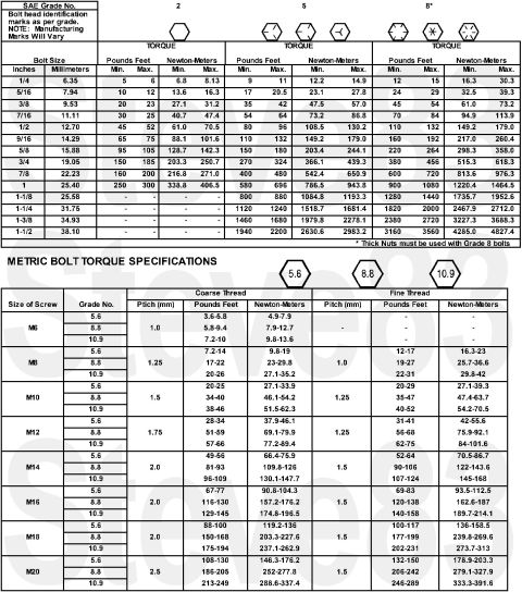
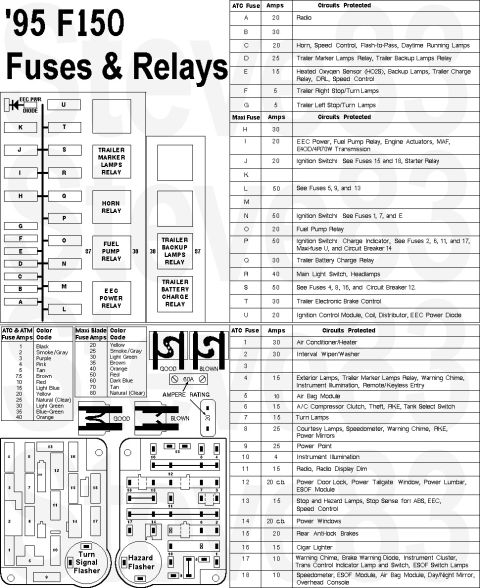
1992 Ford E4OD Transmission Fault Code Diagnosis Chart - DTC List & Symptoms Ford Bronco Sliding Caliper Pin Installation Diagram - Brake Grease & Pin Tabs Ford Door Lock Cylinder Replacement - Clip Removal & Standard DL140T Swap 1991-95 Ford Bronco/F-Series EEC-IV 3-Digit DTC Codes 335-998 (Page 2) 1991-95 Ford Bronco/F-Series EEC-IV 3-Digit DTC Code List & Definitions Ford Camber/Caster Adjuster Cam Rotation Offset Chart - Alignment Bushing Table Brake line flaring tool on tubing with chamfer, bubble flare, double flare and single flare steps Paper drilling template taped to a body panel with 1/4" hole marks and access hole outline over a seat belt an 2000-2006 Suburban / Yukon XL 3rd Row Bench Seat Bracket Installation Guide Ford 5.8L 351 / 6.6L 400 V8 Rocker Arm & Valve Spring In-Chassis Service Ford 351M / 400 V8 Valve Clearance & Hydraulic Tappet Adjustment Procedure Erson Cams camshaft install sheet with oil, break-in procedure and valve spring pressures 40service procedures1980-1986 Ford Bronco More reference 1996 Ford Bronco & F-Series Trailer Wiring Diagram - 7-Pin Connector PinoutWiring diagram Ford accessories catalog page with cellular mobile telephone and 40-channel CB emergency radioBrochure Ford door certification label dated 11/95 with GVWR 6300LB, P235/75R15XL tires and VIN 1FMEU15H4TLA76236Spec plate 1992-96 Ford F-150/F-250/F-350 2WD Front Sway Bar Diagram & Part NumbersExploded parts Smallblock V8 Coolant Flow Diagram - Ford Engine Cooling Path SchematicSchematic 1996 Ford Bronco/F-Series Starting System - Section 03-06 ContentsManual page Trim panel hole layout photos for positions A, B and C with tape measure readings from the body lineBlueprint Ford 1996 5.8L vehicle information decal with vacuum hose routing diagram and ASF-32P plugVacuum routing SAE and metric bolt torque specification chart by grade in lb-ft and N-mTorque spec '95 F150 fuse and relay chart with fuse panel layout, ATC and Maxi fuse amp tablesFuse chart

Caliper Pin Installation
IF THE IMAGE IS TOO SMALL, click it.

1. Install the caliper on the spindle, making sure the mounting surfaces are free of dirt and lubricate the caliper grooves (not the spindle/knuckle) with Disc Brake Caliper Slide Grease D7AZ19590A (XG3) or equivalent.
2. Position pin with the pin retention tabs oriented adjacent to the spindle groove (NOT the caliper).
3. Tap the pin on the outboard end with a hammer. Continue tapping the pin inward until the retention tabs on the sides of the pin contact the spindle face. Repeat procedure for the lower pin. CAUTION: During the installation procedure do not allow the tabs of the caliper pin to be tapped too far into the spindle groove. If this happens it will be necessary to tap the other end of the caliper pin until the tabs snap into place. The tabs on each end of the caliper pin MUST be free to catch on the spindle flanks.
4. If removed, install the brake hose to the caliper and bleed the brakes.
5. Install the wheel and tire assembly. Tighten the lugnuts to specification.
6. Lower the vehicle, check the brake fluid level and fill as necessary. Pump brake pedal and check brakes for proper operation.

See also:
.

Part of 1980-1986 Ford Bronco Service Procedures

Owner caption · Photo 6408 of 6546

This document is an illustrated service diagram titled "Caliper Pin Installation," showing how a disc brake caliper retaining pin is installed on a sliding-caliper front brake assembly. The left illustration shows the caliper pin being inserted between the caliper and the spindle (knuckle), with callouts identifying the spindle (knuckle), brake pad, and caliper, and highlighting (in magenta) the surfaces where brake grease should be applied to the pin. The right illustration is a close-up view of the pin seated between the caliper and spindle flank, with a callout labeling the spindle flank and an instruction box stating: "After installation inspect to insure that pin tabs are free to contact spindle flanks on each end of pin." A reader learns where to apply brake grease on the caliper pin, the orientation of the pin relative to the spindle and caliper, and the critical post-installation inspection point, verifying that the pin's retaining tabs are free to contact the spindle flanks at both ends. The diagram contains no part numbers, torque specifications, or explicit year/model applicability, but it was uploaded to a 1983 Ford Bronco gallery alongside other brake-system reference scans.

Is this accurate? Sign in to help verify it.

Frequently asked questions

Where should brake grease be applied when installing a caliper pin?
The diagram highlights the caliper pin's contact surfaces (shown in magenta on the pin where it slides between the caliper and spindle/knuckle) as the areas to coat with brake grease.
What should be inspected after installing the caliper pin?
After installation, inspect to insure that the pin tabs are free to contact the spindle flanks on each end of the pin.
What components are involved in the caliper pin installation shown?
The diagram labels the spindle (knuckle), the spindle flank, the brake pad, the caliper, and the caliper pin coated with brake grease.
Where does the caliper pin sit in the assembly?
The pin slides in between the caliper and the spindle (knuckle), with its tabs engaging the spindle flanks at each end.
Comments

No comments yet.

More 1980-1986 Broncos