Home/
Registry/
Ford/
Bronco/
1980-1986/
1985 Ford Bronco/
Photo
supermotors.net/registry/media/156837
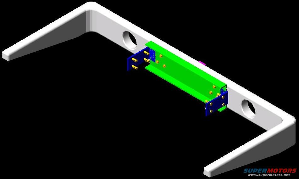
1985 Ford Bronco Rear Bumper 3D CAD Model - Crossmember & Bracket Assembly
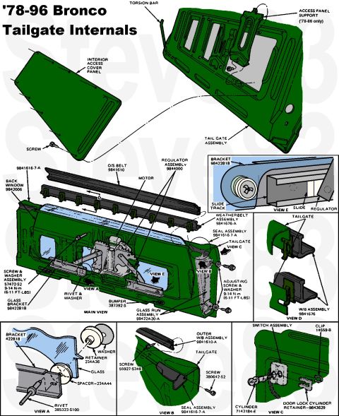
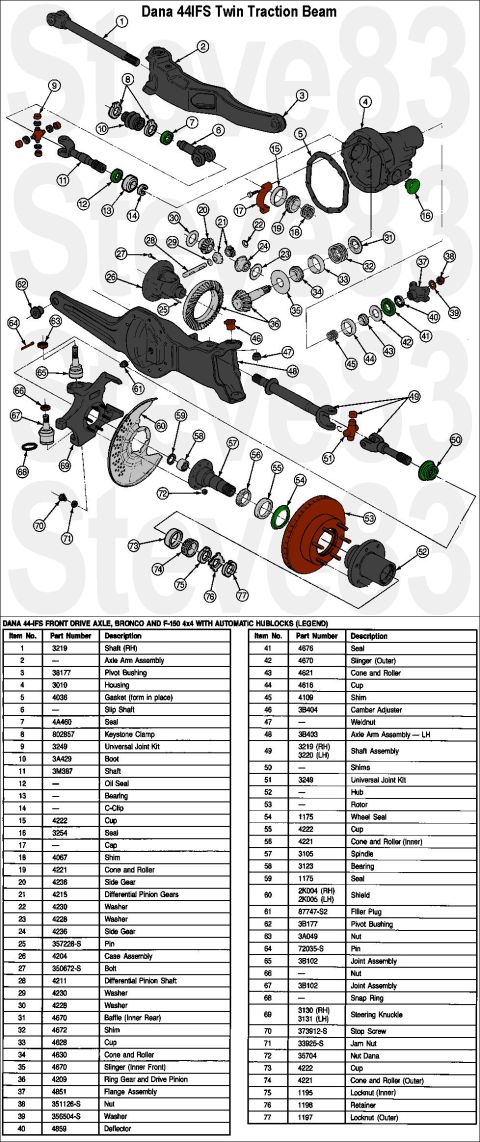
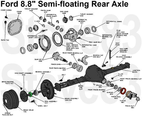
Reference · 1980-1986 BroncoAll 61 exploded parts diagrams


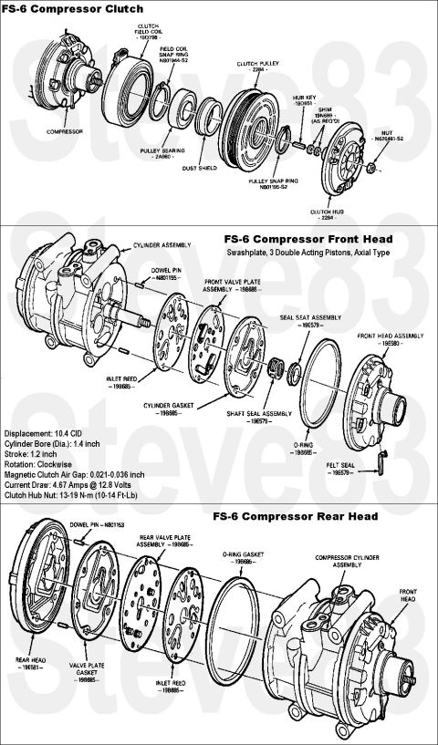
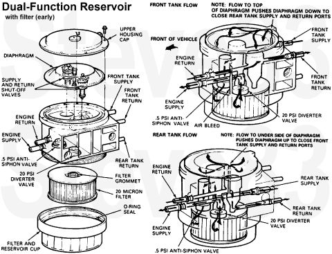


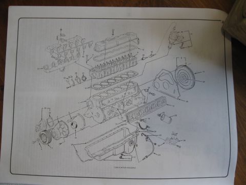


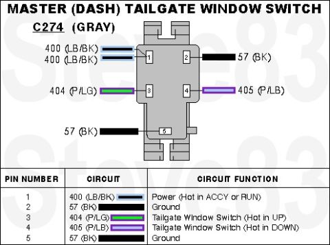

3D CAD model of a fabricated crossmember and bracket assembly showing component placement and mounting hardware.
Part of 1980-1986 Ford Bronco Exploded Parts Diagrams
This document is not a scanned text page but a computer-generated 3D model rendering, apparently of a rear bumper assembly for a Ford Bronco (per the uploader's filing, filename 'BUMPER 2 REAR.jpg'). The render shows a long white C-channel bumper shell viewed from an isometric angle, with a circular hole visible on each face of the channel. Mounted at the center rear of the bumper is a green rectangular crossmember or mounting bar. This green bar attaches at both ends via blue bracket plates, each secured with multiple yellow-rendered bolts or fasteners (roughly four to six per bracket). A small magenta component appears near the right-hand bracket area. There is no visible text of any kind: no part numbers, dimensions, torque specifications, legends, or annotations. A reader can learn the general construction concept of this rear bumper, an outer formed shell reinforced by a bolted-in central crossbar with end brackets, and how the fasteners are arranged, but no specific specifications can be extracted. It appears to be one image in a multi-part set (companion file BUMPER1-2.jpg) documenting a custom or modeled bumper design.
Is this accurate? Sign in to help verify it.
Frequently asked questions
- What does this image show?
- A 3D CAD-style rendering of a rear bumper assembly: a white C-channel bumper shell with a green central crossmember bar attached by blue end brackets and yellow bolts.
- Does the image include part numbers or dimensions?
- No. The rendering contains no visible text, part numbers, dimensions, or torque values.
- How is the green crossbar attached to the bumper?
- Via blue bracket plates at each end of the bar, each fastened with multiple yellow-rendered bolts.
- Are there mounting holes in the bumper shell?
- Yes, a round hole is visible on each face of the white C-channel bumper near the center section.
No comments yet.