Home/
Registry/
Ford/
Bronco/
1980-1986/
“Still Pending”/
Photo
supermotors.net/registry/media/825055
Ford F250 F350 4x4 Front Stabilizer Bar (Sway Bar) Exploded Diagram - Fig 11.15
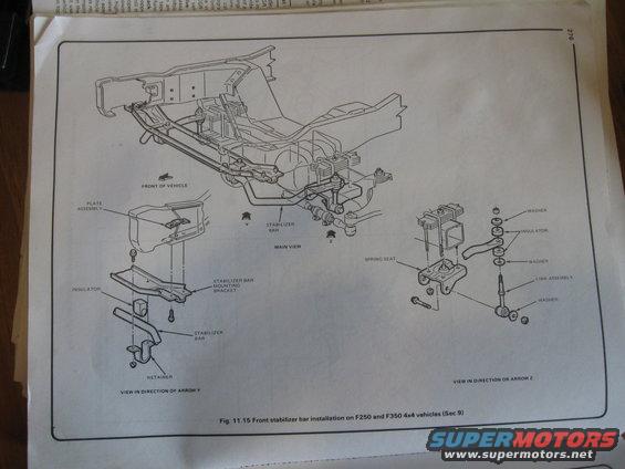
Assembly diagram of front stabilizer bar installation on F-250/F-350 4x4 showing brackets, insulators, links and washers in multiple views.
This is a scanned page (page 276) from a repair manual showing Figure 11.15, an exploded parts diagram of the front stabilizer bar (sway bar) installation on Ford F250 and F350 4x4 vehicles, referenced to Section 9 of the manual. The page contains three related illustrations: a main isometric view of the front frame and axle area showing the stabilizer bar's location relative to the front of the vehicle, with arrows Y and Z indicating the viewing directions for the two detail views. The 'View in direction of arrow Y' detail shows the frame-side mounting, calling out the plate assembly, insulator, stabilizer bar mounting bracket, stabilizer bar, and retainer. The 'View in direction or arrow Z' detail shows the axle/spring-seat end, calling out the washers, insulators, spring seat, and link assembly with its hardware stack (washer/insulator/washer arrangement on the end link). A reader can learn the correct order and orientation of all stabilizer bar mounting components, brackets, bushings (insulators), retainers, and end-link hardware, useful when removing, replacing, or reassembling the front sway bar on these 4x4 trucks. No torque values, part numbers, or fuse data appear on this page.
Is this accurate? Sign in to help verify it.
Frequently asked questions
- What does this diagram show?
- Figure 11.15 shows the front stabilizer bar installation on F250 and F350 4x4 vehicles, with a main view plus two detail views (direction of arrow Y and arrow Z).
- What parts make up the frame-side stabilizer bar mount?
- Per the arrow Y view: a plate assembly, insulator, stabilizer bar mounting bracket, the stabilizer bar itself, and a retainer.
- How is the stabilizer bar end link assembled?
- Per the arrow Z view, the link assembly passes through a stack of washers and insulators (washer, insulator, washer arrangement) and attaches at the spring seat.
- Which manual section does this figure belong to?
- The caption references Section 9 (Sec 9); the figure is numbered 11.15 and appears on page 276.
Comments
More from this build









No comments yet.