Home/
Registry/
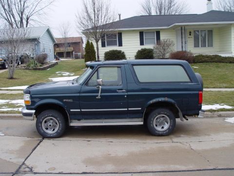
Ford/
Bronco/
1992-1996/
“badassbronco”/
Photo
supermotors.net/registry/media/209723
DTC P0102 MAF Sensor Diagnostic: GM 2.5L (LE8) Engine Controls Test Table

GM engine-controls DTC P0102 test description and start of the diagnostic table: step-by-step MAF signal-circuit checks with scan-tool values such as 2.5-4.6 g/s MAF reading and 8 V signal.
Part of 1992-1996 Ford Bronco Service Procedures
This scanned service-manual page (labeled "Engine Controls - 2.5L (LE8), 6-1451") documents the diagnostic procedure for DTC P0102, a mass air flow (MAF) sensor circuit low-frequency fault. The Test Description explains selected steps of the diagnostic table: Step 1 is the Diagnostic System Check-Engine Controls and Freeze Frame capture, Step 2 determines if the fault is present, Step 7 checks for an open or short in the MAF signal circuit between the MAF sensor and the PCM, and Step 10 verifies whether the malfunction is still present using the scan tool's Not Ran Since Code Cleared list in DTC Information. The step-by-step diagnostic table (Steps 1-6 visible) walks through checking the MAF reading with a scan tool at closed throttle (expected 2.5-4.6 g/s), clearing DTCs and re-running the diagnostic, measuring MAF ignition feed voltage with the connector disconnected (expected B+), backprobing the MAF signal circuit at the PCM while idling (expected 1.5-1.8 V), and repairing an open or short in the MAF ignition feed circuit per Wiring Repairs. Schematic references cited are the IAC Valve, VSS, and MAP Sensor. Each step routes the technician to the next step based on Yes/No results.
Is this accurate? Sign in to help verify it.
Frequently asked questions
- What is the specified MAF reading at closed throttle for DTC P0102 diagnosis?
- With the engine running, scan tool installed, and throttle closed, the mass air flow (MAF) sensor parameter should read 2.5-4.6 g/s (Step 2).
- What voltage should the MAF sensor ignition feed circuit show?
- With the MAF connector disconnected and ignition ON (engine OFF), the ignition feed circuit measured with a DMM to ground should be near B+ (battery voltage) per Step 4.
- What voltage should the MAF signal circuit read at the PCM while idling?
- Backprobing the MAF sensor signal circuit at the PCM with a DMM while the engine idles should show 1.5-1.8 V (Step 5).
- How do you verify the P0102 diagnostic has run after clearing codes?
- Monitor the Not Ran Since Code Cleared selection in the DTC Information menu on the scan tool. If P0102 appears in the list, the diagnostic has not yet run; if it does not appear, it has run. Check Current or Pending status to determine pass/fail.
- What do you do if the MAF ignition feed voltage is not near B+?
- Go to Step 6: repair the open or short circuit in the MAF sensor ignition feed circuit, referring to Wiring Repairs in Wiring Systems, then go to Step 10.
Comments
More from this build











No comments yet.