Home/
Registry/
Ford/
Bronco/
1992-1996/
“badassbronco”/
Photo
supermotors.net/registry/media/292556
Electric Fuel Pump Relay Wiring Diagram - Bosch Relay, Oil Pressure Switch, Ford Bronco

Reference · 1992-1996 BroncoAll 411 wiring diagrams
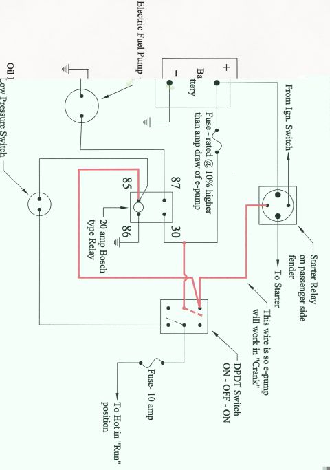




Hand-drawn wiring diagram showing an electric fuel pump wired through a Bosch relay, DPDT switch, fuse and starter relay with color-coded leads.
Part of 1992-1996 Ford Bronco Wiring Diagrams
This document is a hand-drawn wiring diagram (scanned, rotated 90°) showing how to wire an aftermarket electric fuel pump ("e-pump") on a vehicle, uploaded to a 1992 Ford Bronco gallery. The circuit uses a 20 amp Bosch-type relay (terminals 85, 86, 87, and 30) to power the electric fuel pump. Battery positive feeds the pump circuit through a fuse that the diagram instructs be rated at 10% higher than the amp draw of the e-pump. The relay coil (terminal 85) is controlled through a DPDT ON-OFF-ON switch, which receives power through a 10 amp fuse from a source that is "Hot in Run" position. A highlighted (red) wire runs from the starter relay on the passenger side fender to the DPDT switch so the electric pump will also operate while the ignition is in "Crank." An oil low-pressure switch is included in the circuit as a safety, and the starter relay is shown with connections "From Ign. Switch" and "To Starter." Grounds are shown for the battery, relay terminal 86, and the pump circuit. The diagram gives no year, make, model, part numbers, or wire colors, only component labels and fuse ratings.
Is this accurate? Sign in to help verify it.
Frequently asked questions
- What size fuse should I use for the electric fuel pump power feed?
- The diagram says to use a fuse rated at 10% higher than the amp draw of the e-pump on the battery feed, plus a 10 amp fuse on the switched "Hot in Run" circuit feeding the DPDT switch.
- What relay is used to power the electric fuel pump?
- A 20 amp Bosch-type relay with standard terminals 85, 86, 87, and 30. Terminal 86 goes to ground, 87 feeds the pump circuit, and 30 gets fused battery power.
- How does the fuel pump run while cranking the engine?
- A wire (highlighted in the diagram) runs from the starter relay on the passenger side fender to the DPDT switch; the diagram notes "This wire is so e-pump will work in 'Crank'."
- What kind of switch controls the pump circuit?
- A DPDT (double pole, double throw) ON - OFF - ON switch, fed through a 10 amp fuse from a circuit that is hot in the "Run" position.
- Is there a safety cutoff in this fuel pump wiring?
- Yes, an oil low pressure switch is wired into the circuit along with the relay, so the pump control passes through the oil pressure switch.





No comments yet.