1989 Dodge Pickup 5.9L Cummins Fuel Injection Pump Install & Timing - Page 3

Reference · 1992-1996 BroncoAll 143 service procedures
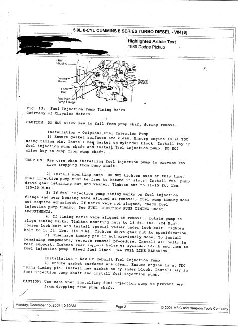
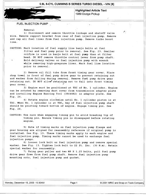




Service procedure page continuing fuel injection pump installation and timing steps for a 5.9L Cummins diesel.
Part of 1992-1996 Ford Bronco Service Procedures
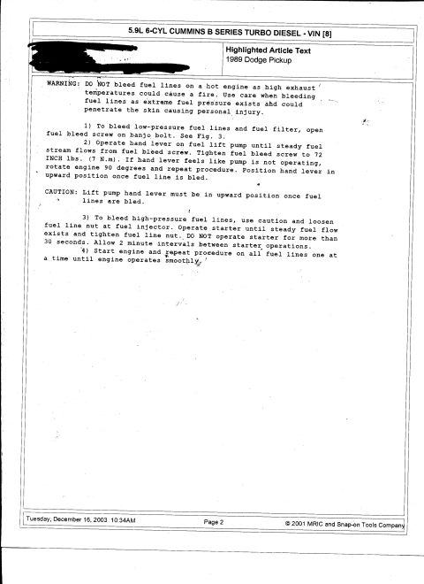
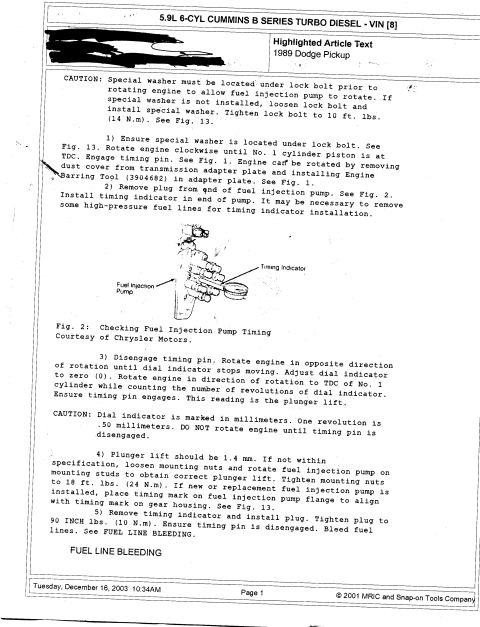
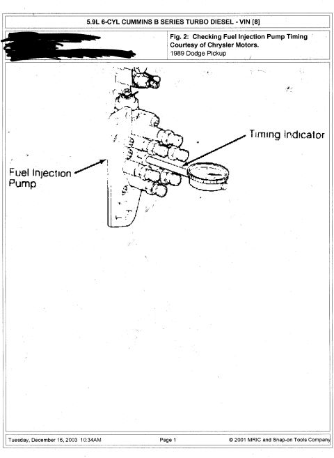
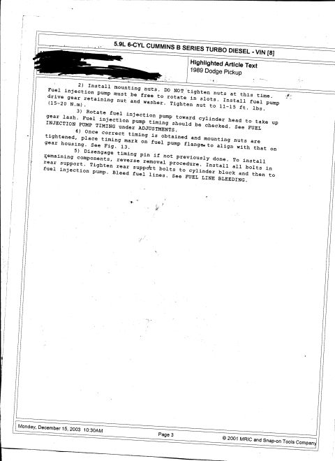
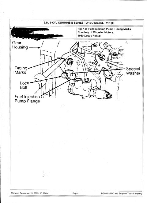
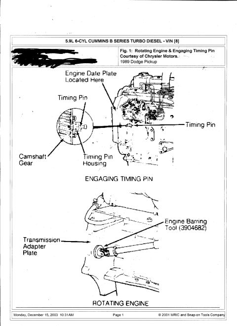
This document is page 3 of a service procedure for the 5.9L 6-cylinder Cummins B Series turbo diesel engine (VIN code 8) as installed in a 1989 Dodge Pickup. The page covers the final steps (steps 2 through 5) of a fuel injection pump installation procedure. Step 2 instructs installing the mounting nuts without tightening them so the pump can rotate in its slots, then installing the fuel pump drive gear retaining nut and washer and torquing it to 11-15 ft. lbs. (15-20 N.m). Step 3 directs rotating the pump toward the cylinder head to take up gear lash and checking fuel injection pump timing (referencing FUEL INJECTION PUMP TIMING under ADJUSTMENTS). Step 4 covers aligning the timing mark on the fuel pump flange with the mark on the gear housing (referencing Fig. 13) after correct timing is obtained and nuts are tightened. Step 5 covers disengaging the timing pin, reversing the removal procedure for remaining components, tightening rear support bolts to the cylinder block and then to the pump, and bleeding the fuel lines (referencing FUEL LINE BLEEDING). The page is dated December 15, 2003 and is copyrighted 2001 MRIC and Snap-on Tools Company. The top-left portion of the page has been blacked out by hand.
This document covers 1989, which may differ from this 1992 Ford Bronco.
Is this accurate? Sign in to help verify it.
Frequently asked questions
- What is the torque spec for the Cummins 5.9L fuel pump drive gear retaining nut?
- The document specifies tightening the fuel pump drive gear retaining nut to 11-15 ft. lbs. (15-20 N.m).
- Should the fuel injection pump mounting nuts be tightened immediately during installation?
- No. The document says DO NOT tighten the mounting nuts at that time, the fuel injection pump must remain free to rotate in its slots until timing is set.
- How is gear lash taken up when installing the injection pump?
- Rotate the fuel injection pump toward the cylinder head to take up gear lash, then check fuel injection pump timing (see FUEL INJECTION PUMP TIMING under ADJUSTMENTS).
- What is done after correct pump timing is obtained?
- Once correct timing is obtained and the mounting nuts are tightened, place a timing mark on the fuel pump flange to align with the mark on the gear housing (see Fig. 13).
- What are the final steps after installing the injection pump?
- Disengage the timing pin if not previously done, reverse the removal procedure for remaining components, install all bolts in the rear support (tightening to the cylinder block first, then to the pump), and bleed the fuel lines per FUEL LINE BLEEDING.





No comments yet.