Home/
Registry/
Ford/
Bronco/
1992-1996/
“badassbronco”/
Photo
supermotors.net/registry/media/176258
John Deere H27178 Exploded Parts Diagram - Hub/Shaft Assembly Callouts 1-28B

Reference · 1992-1996 BroncoAll 169 exploded parts diagrams
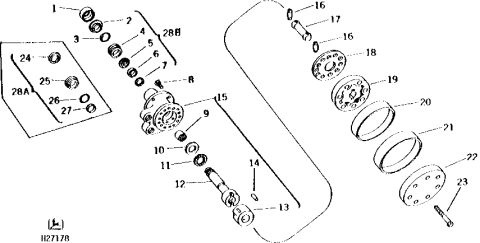
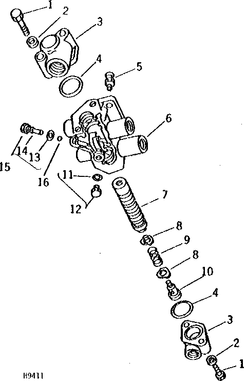

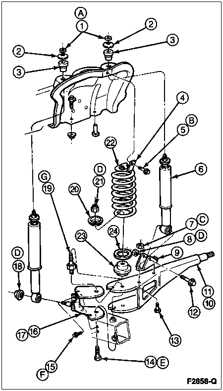
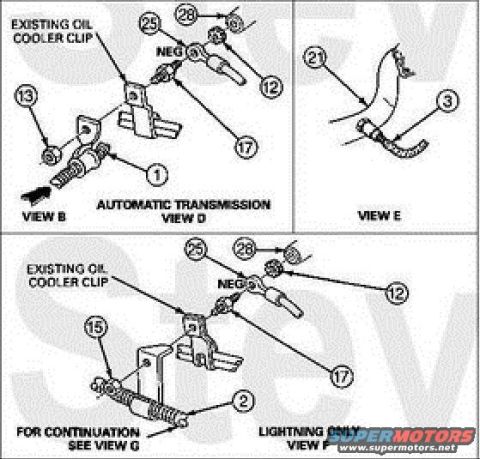
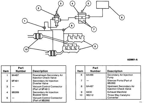
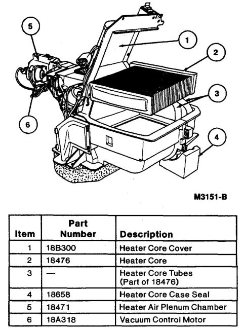
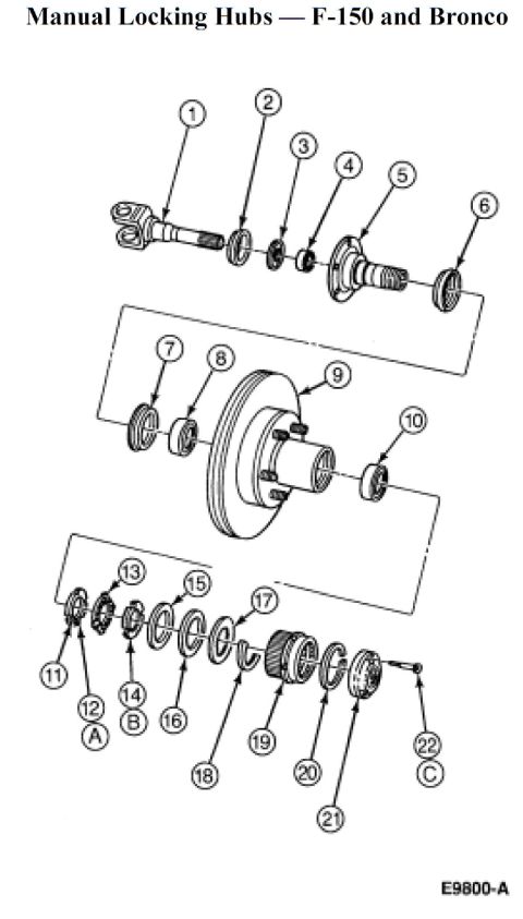
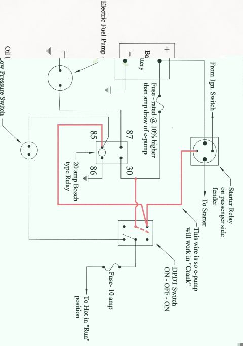




Line-art exploded parts breakdown of a hydraulic motor or pump showing shaft, rotor, seals and end caps with numbered callouts.
Part of 1992-1996 Ford Bronco Exploded Parts Diagrams
This document is an exploded-view parts diagram (illustration ID H27178) bearing a John Deere logo in the lower-left corner. It shows a rotating assembly, apparently a hub/motor or planetary-style unit, broken down into its individual components with numbered callouts from 1 through 28B. The main stack includes small ring/seal/bearing items (1-7, bracketed as group 28B), a flanged hub or housing with a bolt circle (15), a bushing and bearings (9-11), a splined shaft with a yoke or coupler (12-13), a small pin or clip (14), pins and a spacer (16, 17), perforated discs or plates (18, 19), two large rings or bands (20, 21), a drilled end plate or cover (22), and a bolt or stud (23). An inset box labeled 28A groups four additional small ring/seal items (24-27). No part numbers, part names, torque values, or applicability text appear on the drawing, it is a callout-only illustration that would normally accompany a separate parts list keying each number to a part number and description. The image ID H27178 matches the upload filename, and the file appears to be one page of a multi-page parts reference set.
Is this accurate? Sign in to help verify it.
Frequently asked questions
- What does this diagram show?
- An exploded view of a rotating hub/shaft assembly with numbered callouts 1 through 28B, including bearings, seals, a flanged hub (15), a splined shaft with coupler (12-13), discs (18-19), rings (20-21), an end plate (22), and a bolt (23).
- Does the diagram include part numbers or a parts list?
- No. It contains only numbered callouts and the illustration ID H27178; there is no legend, part number list, or descriptions on this page.
- What do the labels 28A and 28B refer to?
- They are group callouts: 28B brackets items 1-7 in the main stack, and 28A is an inset box grouping items 24-27.
- What brand is this diagram from?
- It carries a John Deere leaping-deer logo in the lower-left corner along with the illustration number H27178.






No comments yet.