1978 Ford Bronco Power Distribution Wiring Diagram - Fuse Panel & Splice Index
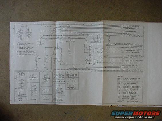
Foldout electrical wiring diagram sheet showing vehicle circuits, connectors and component legends.
Part of 1978-1979 Ford Bronco Wiring Diagrams
This is a scanned fold-out page from a Ford factory electrical vacuum/wiring manual, titled "Electrical System: Power Distribution," with a title-block date of 7-19-78 (superseding 7-8-78), consistent with a 1978 model-year Ford truck/Bronco application. The schematic traces battery power from the standard 12-volt battery (and an optional auxiliary 12-volt battery with dual battery relay and accessory safety relay) through the starter motor relay, fuse links, junction block, ignition switch (START/RUN/OFF/ACCY positions), headlamp switch, and the fuse panel. An upper-left legend maps fuse positions F1-F13 with amp ratings and circuits, including panel lamps/cluster illumination, heater or A/C, seat belt, directional signals, dome/courtesy/glove box/underhood lamps and cigar lighter, turn signal flasher, accessory feeds (speed control, heated backlight relay, marker lamp relay, dual battery relay, 4WD indicator), back-up lamps/windshield washer pump, and radio. Right-edge callouts list destination circuits (power tailgate, trailer relays, alternator/regulator, throttle solenoid, A/C-heater, radio, flashers, etc.). Lower panels give connector-by-connector detail boxes with wiring harness part numbers (14401, 14405, 14A005, 14300, 14301) and physical locations, plus a ground-cable table (G-101 through G-1201) and a splice index (S-101 through S-1201) identifying where each splice sits in the harness. Fine print is only partially legible at this scan resolution.
Is this accurate? Sign in to help verify it.
Frequently asked questions
- What system does this 1978 Ford wiring diagram cover?
- It is the Electrical System, Power Distribution schematic, showing battery, starter motor relay, fuse links, junction block, ignition switch, headlamp switch, and fuse panel feeds, dated 7-19-78.
- Does the diagram show fuse panel positions and amp ratings?
- Yes. A legend lists fuse positions F1-F13, e.g. F2 = 15 amp panel lamp/cluster & panel illumination, F4 = 7.5 amp seat belt, F13 = 7.5 amp radio; F1 and F6 are blank.
- Does this diagram cover a dual/auxiliary battery setup?
- Yes. It shows a 12-volt battery (standard) and a 12-volt battery (auxiliary) with a dual battery relay and accessory safety relay, including connector locations on the L.H. fender apron.
- Where are the grounds located according to the document?
- The Ground Cables table lists G-101 (eyelet attached to engine), G-103 (battery cable to R.H. fender apron), G-104 (eyelet on dash panel, left of center), and G-1201 (eyelet in engine compartment, L.H. side on dash panel).
- What are the ignition switch positions shown?
- The ignition switch detail lists positions: START, RUN, OFF, and ACCY.
Comments
More from this build









No comments yet.