Ford EEC Self-Test Connector Diagram - DLC & STI Jumper Wire (1992 Bronco)
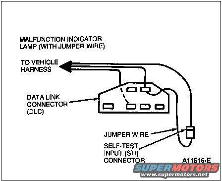
Ford EEC self-test diagram: jumper wire bridging the data link connector (DLC) self-test input (STI) to vehicle harness so the malfunction indicator lamp flashes diagnostic codes.
Part of 1992-1996 Ford Bronco Wiring Diagrams
This document is a labeled line-art illustration showing how to connect a jumper wire for initiating the EEC self-test procedure. It depicts the Data Link Connector (DLC), a multi-pin diagnostic connector with several rectangular terminals, along with the Self-Test Input (STI) connector, a separate single-wire connector. A jumper wire is shown bridging the STI connector to a terminal on the DLC. The diagram also labels a Malfunction Indicator Lamp connection (with jumper wire) and shows wiring leading to the vehicle harness, indicated by an arrow. The figure reference number A11516-E appears in the lower right corner. A reader can learn the physical identification and relative positions of the DLC and STI connectors, and how the jumper wire is used between them to trigger self-test diagnostics, the method used to pull diagnostic trouble codes on Ford EEC-IV systems. The document itself contains no year, model, engine, or wire color information; it was uploaded to a 1992 Ford Bronco gallery as part of a larger set of factory-style reference scans. No pin numbers, torque values, or part numbers other than the figure code are shown.
Is this accurate? Sign in to help verify it.
Frequently asked questions
- What connectors are shown in this self-test diagram?
- The Data Link Connector (DLC) and the Self-Test Input (STI) connector, plus a Malfunction Indicator Lamp connection with jumper wire.
- How is the jumper wire used?
- The diagram shows a jumper wire connecting the Self-Test Input (STI) connector to the Data Link Connector (DLC) to initiate the self-test.
- Where do the wires from the connectors go?
- The diagram shows the wiring leading 'TO VEHICLE HARNESS,' indicated by an arrow.
- Is there a figure reference number on this diagram?
- Yes, the figure is identified as A11516-E in the lower right corner.
Comments
More from this build








No comments yet.