1992 Ford Bronco Cruise Control Wiring Diagram - Servo, Amplifier & Wire Colors

Reference · 1992-1996 BroncoAll 411 wiring diagrams
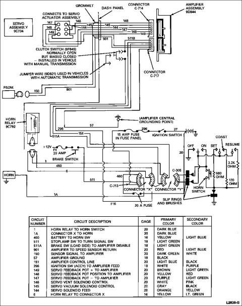
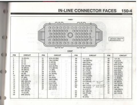
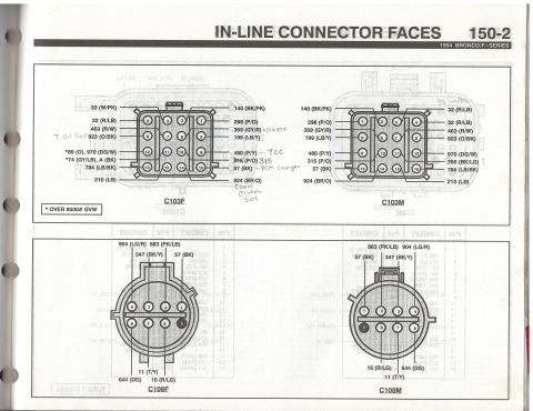
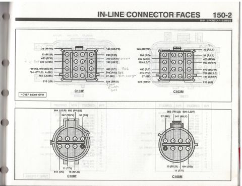
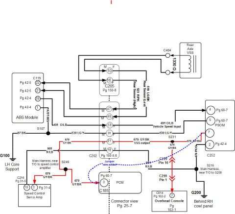



Ford cruise/speed control wiring diagram: servo assembly 9C734, amplifier 90R94, clutch switch 9F645, horn relay, 15A and 20A fuses, with full circuit/color chart.
Part of 1992-1996 Ford Bronco Wiring Diagrams
This document is a Ford speed control (cruise control) system wiring schematic, uploaded as applicable to a 1992 Ford Bronco. It shows the vacuum-servo type cruise control circuit, including the servo assembly (part 9C734), amplifier assembly (9D844), connectors C-714, C-717, C-713, C-305, and connectors X and Y, plus the dash panel grommet pass-through. It documents the clutch switch (9F645, normally open but biased closed) used on manual transmission vehicles and the jumper wire (9D821) used on automatic transmission vehicles. Power feeds shown include a 15 amp fuse in the fuse panel from the ignition switch (ACCY), a 20 amp fuse F1 through the brake switch, and a 20 A fuse at F16. The steering wheel switch circuit shows OFF, ON, SET, COAST, and RESUME functions with resistor values of 2.2K, 680, and 120 ohms, routed through the horn switch, slip rings and brushes, and horn relay (9C792). A complete circuit legend table lists 17 circuit numbers (1, 1A, 460, 511, 511A, 901, 150, 57, 151, 296, 149, 148, 147, 146, 145, 144, 6) with descriptions, wire gauges (16-20 AWG), and primary/secondary wire colors. The PSOM (speed sensor) connects via circuits 150 and 901. Drawing reference: L2839-G.
Is this accurate? Sign in to help verify it.
Frequently asked questions
- What wire color is circuit 145 (servo vacuum solenoid control)?
- Circuit 145 is 20 gauge, gray with a black secondary color, running the servo vacuum solenoid control.
- What fuses power the cruise control system in this diagram?
- A 15 amp fuse in the fuse panel feeds the amplifier from the ignition switch (circuit 296), fuse F1 (20 amp) feeds the brake switch on the +12V line, and a 20 A fuse is shown at position F16.
- How does the system differ between manual and automatic transmissions?
- Manual transmission vehicles use a clutch switch (part 9F645), normally open but biased closed; automatic transmission vehicles use a jumper wire (part 9D821) in its place.
- What are the resistor values in the steering wheel cruise switch?
- The switch circuit shows 2.2K ohm, 680 ohm, and 120 ohm resistors for the ON, SET/COAST, and RESUME functions.
- What part numbers appear for the main cruise control components?
- Servo assembly 9C734, amplifier assembly 9D844, clutch switch 9F645, jumper wire 9D821, and horn relay 9C792.






No comments yet.