Ford Bronco Overhead Console Wiring Diagram - C914 Compass/Temp Module Pinout

Reference · 1992-1996 BroncoAll 411 wiring diagrams
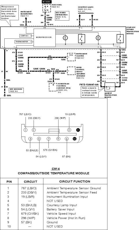







Wiring diagram of the compass/outside temperature module showing color-coded circuits, connector C914 pinout and function table.
Part of 1992-1996 Ford Bronco Wiring Diagrams
This document is a wiring diagram and connector pinout for a Ford compass/outside temperature module (overhead console). The top portion is an EVTM-style schematic showing the microprocessor-based module that controls dome lamp, compass, and thermometer functions. Power comes from fuse panel fuse 18 (10A, hot in run) on circuit 296 (W/P), with instrument illumination input on circuit 19 (LB/R) and courtesy lamp connections on circuits 54 (LG/Y) and 53 (BK/LB). The vehicle speed input (circuit 679, GY/BK) is shared with the instrument cluster PSOM, the speed control servo/amplifier assembly, and the powertrain control module (PCM). The ambient temperature sensor (part F87Z-12A647-AA) connects via circuits 233 (DB/Y) and 767 (LB/O) through connectors C206, C223, C202, and C131, and sends a signal to the overhead console indicating outside air temperature. Ground is via circuit 57 (BK) through splice S901 to G201. The lower half shows the C914 connector face for the compass/outside temperature module and a complete 10-pin pinout table listing each circuit number, wire color, and function, including not-used pins 4 and 10. Cross-references to related pages (power distribution 13-10/13-11, grounds 10-6, instrument cluster 60-7, speed control 31-2, PCM 24-2/25-2) are included.
Is this accurate? Sign in to help verify it.
Frequently asked questions
- What fuse powers the compass/outside temperature module?
- Fuse 18, a 10A fuse in the fuse panel (page 13-3), hot in run, feeding circuit 296 (W/P) to pin 8 of connector C914.
- What is the pinout of the C914 compass/outside temperature module connector?
- Pin 1: 767 (LB/O) Ambient Temperature Sensor Ground; Pin 2: 233 (DB/Y) Ambient Temperature Sensor Feed; Pin 3: 19 (LB/R) Instrument Illumination Input; Pin 4: not used; Pin 5: 53 (BK/LB) Courtesy Lamp Input; Pin 6: 54 (LG/Y) Battery Saver Input; Pin 7: 679 (GY/BK) Vehicle Speed Input; Pin 8: 296 (W/P) Vehicle Power (Hot in Run); Pin 9: 57 (BK) Ground; Pin 10: not used.
- What is the part number of the ambient temperature sensor?
- F87Z-12A647-AA. It sends a signal to the overhead console to indicate outside air temperature, via circuits 233 (DB/Y) and 767 (LB/O).
- What other modules share the vehicle speed input circuit 679 (GY/BK)?
- Circuit 679 (GY/BK) also connects to the instrument cluster PSOM (page 60-7), the speed control servo/amplifier assembly (page 31-2), and the powertrain control module PCM (pages 24-2, 25-2).
- Where does the module ground?
- Pin 9 uses circuit 57 (BK), which runs through splice S901 to ground G201 (see grounds page 10-6).






No comments yet.